Detector Simulations: Difference between revisions
| (3 intermediate revisions by the same user not shown) | |||
| Line 129: | Line 129: | ||
Figure 2 shows an example of the signals induced on neighbouring anode wires. The pads facing the wire involved in the electron avalanche receive a signal contribution proportional to their distance from the avalanche region. The signal calculation for each electrode is repeated for each electron drifting to the anode wires and, after the appropriate summation, stored in a ROOT file for later analysis. | Figure 2 shows an example of the signals induced on neighbouring anode wires. The pads facing the wire involved in the electron avalanche receive a signal contribution proportional to their distance from the avalanche region. The signal calculation for each electrode is repeated for each electron drifting to the anode wires and, after the appropriate summation, stored in a ROOT file for later analysis. | ||
== TPC Signal Generation == | |||
=== Objective === | |||
A detailed simulation of the rTPC was set up in Garfield++ in order to understand the electron drift both in the radial field and in the more complex field region near the wires, as well as predict the signals induced on the anode wires and signal pads. | A detailed simulation of the rTPC was set up in Garfield++ in order to understand the electron drift both in the radial field and in the more complex field region near the wires, as well as predict the signals induced on the anode wires and signal pads. | ||
| Line 186: | Line 182: | ||
<li><p>convert anode number, pad number, and electron arrival times to (r,φ,z)-coordinates</p> | <li><p>convert anode number, pad number, and electron arrival times to (r,φ,z)-coordinates</p> | ||
<ol style="list-style-type: decimal;"> | <ol style="list-style-type: decimal;"> | ||
</li></ol> | </li></ol> | ||
=== Time Extraction === | |||
'''Leading Edge Detection''' | '''Leading Edge Detection''' | ||
| Line 253: | Line 249: | ||
# Cosmic tracks are straight lines within the detector volume (most cosmic muons don’t experience large-angle scattering inside the detector) | # Cosmic tracks are straight lines within the detector volume (most cosmic muons don’t experience large-angle scattering inside the detector) | ||
# Cosmic rays enter and leave the detector volume through the sides of the cylinder, i.e. passing by anode wires (this applies for a horizontally mounted TPC like the prototype | # Cosmic rays enter and leave the detector volume through the sides of the cylinder, i.e. passing by anode wires (this applies for a horizontally mounted TPC like the prototype but even for a vertical geometry such tracks are available) | ||
# Ionization from these close passes to anode wires will produce the first signals of a given event, these signals arrive at the entrance and exit wire at approximately the same time. | # Ionization from these close passes to anode wires will produce the first signals of a given event, these signals arrive at the entrance and exit wire at approximately the same time. | ||
From these assumptions the space-time relation can be produced in the following way, only shown for zero magnetic | From these assumptions, the space-time relation can be produced in the following way, only shown for zero magnetic fields, but with some extra care this can be done in the presence of a magnetic field as well: | ||
# Select only events with coincident first signals in two well-separated (groups of) anodes | # Select only events with coincident first signals in two well-separated (groups of) anodes | ||
| Line 268: | Line 261: | ||
Figure 11 shows an example result of this process in comparison to the Garfield++-derived formula. | Figure 11 shows an example result of this process in comparison to the Garfield++-derived formula. | ||
With enough statistics a space-time relation can be extracted e.g. from the peak of the radius distribution for a given drift time, i.e. a slice of the histogram in '''''Figure 9'''''. | With enough statistics, a space-time relation can be extracted e.g. from the peak of the radius distribution for a given drift time, i.e. a slice of the histogram in '''''Figure 9'''''. | ||
[[File:images12.png|509x345px]] | [[File:images12.png|509x345px]] | ||
| Line 310: | Line 303: | ||
The estimated performance of the tracking and vertexing algorithms, determined from the Monte-Carlo simulation, are reported in the Table below. The efficiency with which the reconstruction procedure finds the annihilation vertex (defined as the ratio of the number of reconstructed vertexes to the number of generated ones) is remarkably high, guaranteeing “high statistics” for the experiment. The vertex resolution, which is visualized in Error: Reference source not found suits the physics goal set by the ALPHA-g experiment. | The estimated performance of the tracking and vertexing algorithms, determined from the Monte-Carlo simulation, are reported in the Table below. The efficiency with which the reconstruction procedure finds the annihilation vertex (defined as the ratio of the number of reconstructed vertexes to the number of generated ones) is remarkably high, guaranteeing “high statistics” for the experiment. The vertex resolution, which is visualized in Error: Reference source not found suits the physics goal set by the ALPHA-g experiment. | ||
{| | {| class="wikitable" | ||
|- | |- | ||
! Space point resolution r-φ !! 2 mm | |||
|- | |- | ||
| Space point resolution z | | Space point resolution z ||4 mm | ||
| | |||
|- | |- | ||
| Average number of space points per track | | Average number of space points per track || 132 ± 40 | ||
| | |||
|- | |- | ||
| Vertex resolution r | | Vertex resolution r || (9.1 ± 0.1) mm | ||
| | |||
|- | |- | ||
| Vertex resolution φ | | Vertex resolution φ || (24.0 ± 0.5)° | ||
| | |||
|- | |- | ||
| Vertex resolution z | | Vertex resolution z || (5.0 ± 0.1) mm | ||
| | |||
|- | |- | ||
| Vertex reconstruction efficiency | | Vertex reconstruction efficiency || (94.8 ± 0.3) % | ||
| | |||
|- | |- | ||
| Average Number of Helices per vertex | | Average Number of Helices per vertex || 3.25 ± 0.01 | ||
| | |||
|} | |} | ||
Latest revision as of 20:31, 23 September 2017
Back to Documentation
Table of Figures
Figure 1 - Cross-section view of the ALPHA-g apparatus with the radial TPC 7
Figure 2 - Simulated signals on a set of neighbouring anode wires, demonstrating the opposite-sign induction on neighbours. 8
Figure 3 - Electron drift velocity in different gas mixtures 9
Figure 4 - Pion track (green) emitted in x-direction (φ = 0) and bent by magnetic field, orange lines are a subset of electron drift lines. 10
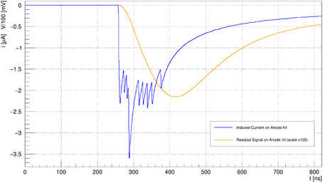
Figure 5 - Anode signal: blue is raw induced current, orange is amplified signal. The spikes that are visible in the raw pulse are indicative of the arrival of individual electron clusters 11
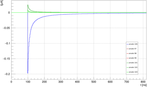
Figure 6 - Signals induced on direct and second neighbouring anodes on both sides of an anode with a "real" signal 12
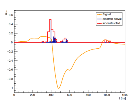
Figure 7 - Deconvolution result of a Garfield++ simulated anode signal. The reconstructed red arrival times reproduce the blue "real" times. 14
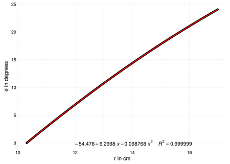
Figure 8 - Electron drift line points in cylindrical coordinates, including quadratic fit 15
Figure 9 - Isochrones, i.e. groups of spacepoints of equal drift time (separation of groups is 50ns) 16
Figure 10 - Isochrones under the influence of diffusion (separation of groups is 200ns) 16
Figure 11 - Radius versus drift time determined from the self-calibration method, the red line represents the results from Garfield++. 18
Figure 12 - Reconstruction of cosmic events from the prototype in r-φ projection. Black points are reconstructed space points, green lines are track fits. 19
Figure 13 - Two orthogonal views of the same pion trajectory in the presence of a magnetic field. The trap volume is shown in yellow. 20
Figure 14 - Vertex resolution, i.e., the distance between the reconstructed vertex and the one simulated in the Monte Carlo simulation. Bottom right is the distribution of the reconstructed vertexes (coloured) in the x-y plane. The distribution of the generated (Monte Carlo) vertexes is the red ring, corresponding to the trap radius 21
Figure 15 - Flowchart for the track finding algorithm 26
Purpose
- The Monte Carlo simulation of the ALPHA-g radial TPC helps to understand the response of the detector to radiation (antihydrogen annihilation products and cosmic rays) and is required to test and develop the analysis, called the reconstruction, of the antihydrogen annihilation vertex.
The results of the simulations will be compared to those of the prototype and the final detector in order to gain insight into their functionality.
Scope
- The current software package is articulated in four parts:
- Simulation of antihydrogen annihilation in the ALPHA-2/g apparatus. (Section 5.1)
- Response of the TPC (including transport of charge particles in the crossed electric-magnetic field and signal generation on anodes and cathodes, Section 5.2)
- Analysis of the simulated signal of the detector (Section 5.3)
- Reconstruction of the vertex (Section 5.4)
Each part takes care of a particular issue related to the development of the detector. While they will be merged into one integrated simulation and a comprehensive analysis framework, they are, for the time being, treated separately.
Definitions and Abbreviations
General acronyms or terms used for the ALPHA-g experiment
| rTPC | Radial Time projection Chamber |
| z | Coordinate along the main axis of the trap and rTPC |
| φ | Azimuthal coordinate, φ = 0 is in direction of cartesian x |
| θ | Angle towards the z-axis |
| r | Radial coordinate in the cylindrical rTPC system |
| pφ | φ component of the pion's original momentum |
| pθ | θ component of the pion's original momentum |
| GEANT4 | GEometry ANd Tracking, particle physics simulation package |
| Garfield++ | Gas detector simulation package |
Table 1 – ALPHA-g Abbreviations
References and Related Documents
[Geant4 (a)] S. Agostinelli et al., “GEANT4: A simulation toolkit”, Nucl. Instrum. Meth. A506, 250–303 (2003).
[Geant4 (b)] J. Allison et al., “Geant4 developments and applications”, Nuclear Science,IEEE Transactions on 53, 270–278 (2006).
[π generation (a)] G. Bendiscioli and D. Kharzeev, “Antinucleon-nucleon and antinucleon-nucleus interaction. A review of experimental data”, La Rivista Del Nuovo Cimento Series 3 17, 1–142 (1994).
[π generation (b)] F. E. James, “Monte Carlo phase space”, tech. rep. (CERN, 1968).
[PAI model] J. Apostolakis et al., “An implementation of ionisation energy loss in very thin absorbers for the GEANT4 simulation package”, Nucl. Instrum. Meth. A453, 597–605 (2000).
[Garfield] R. Veenhof, “Garfield, a drift chamber simulation program”, Conf.Proc. C9306149, 66–71 (1993).
[Gas Detectors] F. Sauli., Principles of Operation of Multiwire Proportional and Drift Chambers. 1977
[Initial TPC simulation] A. Capra, Testing CPT and antigravity with trapped antihydrogen at ALPHA. PhD thesis, York University (2015).
[Helix Fit (a)] P. Avery, “Applied Fitting Theory V: track fitting using the Kalman filter”, CLEO Note CBX92-39 (1992).
[Helix Fit (b)] P. Avery, “Applied Fitting Theory IV”, CLEO Note CBX92-39 (1992).
Studies
Antihydrogen Annihilation Monte Carlo
Identification of antihydrogen annihilation and its location, called the vertex, is a valuable tool to monitor the ALPHA-2/g experiment and to achieve meaningful physics results. This includes the discrimination between antihydrogen annihilation and cosmic rays.
Particle tracking in the ALPHA environment is challenging: the distance between the annihilation point and the first measurement of the annihilation products is of the order of several centimetres and the abundance of material with high density causes a degradation of the tracking performance due to multiple scattering. In addition, this scattering material, with high atomic number, provides also the ideal environment for the high energy photons (produced, e.g., in the instantaneous decay of the neutral pion) to create electron-positron pairs. Since these particles do not directly relate to the antihydrogen annihilation point, they add a challenge to the vertex determination.
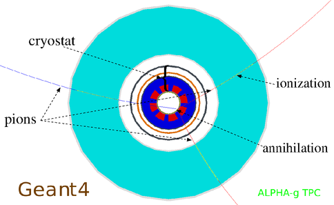
A Monte Carlo simulation of the ALPHA-g radial TPC is performed with the Geant4 simulation package in order to develop and test the reconstruction of the vertex. Initially, the simulation hinged on the determination of an optimal drift radius and pad size. The geometry of the simulation includes all the features of the ALPHA-2 apparatus, in the absence of a complete model for ALPHA-g. The apparatus is immersed in a uniform one Tesla magnetic field. The primary particles are charged and neutral pions, i.e., the antihydrogen annihilation products. Their momenta are assigned by assuming that antihydrogen annihilates at rest. The physical processes taken into account for the simulation include the decay of the neutral pion into two photons, the electron-positron pairs production and the multiple scattering in the ALPHA apparatus. The charged particles reaching the active volume of the ALPHA-g radial TPC ionize the gas according to the photo-absorption ionization (PAI) model. Since Geant4 is not designed to propagate particles under the influence of an electric field, the electrons produced by the charged particles in the gas volume are projected to the anode wires by using data imported from another simulation package – Garfield++.
Figure 1 - Cross-section view of the ALPHA-g apparatus with the radial TPC
The geometry of the ALPHA-g apparatus is borrowed from the current ALPHA design, while the details of the new setup (cryostat, magnets, etc.) are in their final design phase. Of course, one obvious difference with respect to the existing apparatus is that ALPHA-g has its axis parallel to the Earth's gravitational field, i.e., it is vertical.
The main goal of this simulation is to reproduce what happens when an antihydrogen atom escapes the confinement. Therefore, the simulation begins by tracing a number of charged and neutral pions, originating from the antihydrogen annihilation point, through the apparatus, based on well-established physical models.
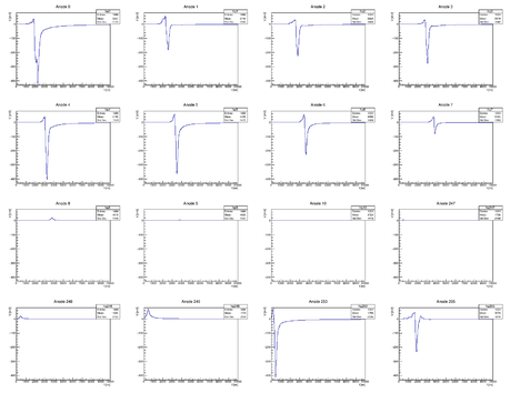
The interaction of the antihydrogen annihilation products with the medium in the gas chamber is described by the PAI model. The primary ionization is spread over the anode wires, based on the Garfield++ simulation of the Lorentz angle. Moreover, the signal induced by an electron avalanching close to an anode is calculated from a signal template obtained in Garfield++. The signals (of opposite polarity) induced into the neighbouring wires are also calculated.
Figure 2 - Simulated signals on a set of neighbouring anode wires, demonstrating the opposite-sign induction on neighbours.
Figure 2 shows an example of the signals induced on neighbouring anode wires. The pads facing the wire involved in the electron avalanche receive a signal contribution proportional to their distance from the avalanche region. The signal calculation for each electrode is repeated for each electron drifting to the anode wires and, after the appropriate summation, stored in a ROOT file for later analysis.
TPC Signal Generation
Objective
A detailed simulation of the rTPC was set up in Garfield++ in order to understand the electron drift both in the radial field and in the more complex field region near the wires, as well as predict the signals induced on the anode wires and signal pads.
Preparation
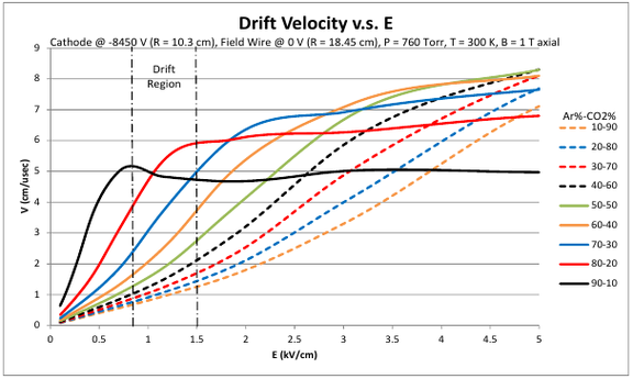
In order to get familiar with the usage of Garfield++ and as a toy model to cross-check modifications to the simulation a planar test geometry was simulated as a first step. Additionally Magboltz (a FORTRAN code called from inside Garfield for solving the Boltzmann equations in electric and magnetic fields) was used to examine key gas parameters like drift velocity (Figure 3) and Lorentz angle for different gas mixtures. Currently all further simulations assume 90:10 Ar/CO2 at atmospheric pressure.
Figure 3 - Electron drift velocity in different gas mixtures
Pion Transport and Ionization
Garfield++ offers the option to create the drift electrons via a realistic ionization model provided by the HEED (High Energy ElectroDynamics) code. This means a primary particle (in our case usually a pion) with a given momentum is sent through the detector volume, reacting to the present electric and magnetic fields, generating ionization clusters of varying size statistically distributed along its track. The code includes secondary ionization caused by high energy primary electrons.
Electron Drift
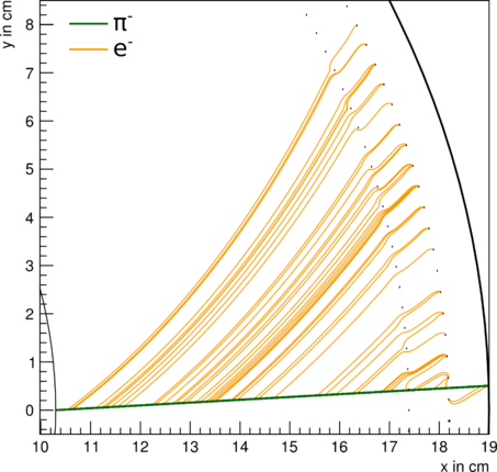
Once created, electrons (and ions) drift along a line defined by the local electric and magnetic fields. Garfield allows the electron drift to be simulated at two basic levels of realism, “Monte Carlo” and “microscopic” or to be solved analytically by the Runge-Kutta-Fehlberg method. In the interest of simulation time, most of the current rTPC simulations use the latter method, although comparison studies have been made, showing mostly good agreement between the methods. An example showing only the first electron generated for every fifth cluster is shown in Figure 4.
Figure 4 - Pion track (green) emitted in x-direction (φ = 0) and bent by magnetic field, orange lines are a subset of electron drift lines.
In order to obtain a formula translating electron drift times and position of the affected anode wires to points of ionization in space single electron drift lines crossing the entire radius range were also recorded.
Signal Calculation
As part of the simulation Garfield can calculate the current a drifting charge induces on electrodes in the vicinity, with the vast majority of the signal in the ALPHA-g setup being caused by ions created by avalanches in the high field near the anode wire. This “raw” signal can then be convoluted with a user-defined response function to simulate the effect of amplifier electronics.
An example of a raw anode signal and the same anode signal convoluted with the amplifier response is shown in Figure 5.
Figure 5 - Anode signal: blue is raw induced current, orange is amplified signal. The spikes that are visible in the raw pulse are indicative of the arrival of individual electron clusters
Additions to Garfield++
It is not feasible in terms of magnet construction to insist on a homogeneous magnetic field over the entire length of the TPC. While homogeneity is good over most of the length, the magnetic field will have a non-negligible radial component near the ends. Unfortunately Garfield++ does not support inhomogeneous magnetic fields out of the box, so some modifications had to be made to add the possibility to create the magnetic field from a three-dimensional field map text file. Currently the available field map is rotationally symmetric, but can be replaced by a more detailed map once one becomes available.
A second shortcoming of Garfield is that while it allows the use of signal pads (or strips) in planar geometry, it does not provide such a feature for a cylindrical chamber. We succeeded in adding this possibility, allowing for a full simulation of all relevant signals in the detector.
Extraction of Space Points
The translation of anode and pad signals into charge space points occurs in three major steps:
extract one or more electron arrival times from the signal
match anode and pad signals by time
convert anode number, pad number, and electron arrival times to (r,φ,z)-coordinates
Time Extraction
Leading Edge Detection
The most obvious method for extracting an electron arrival time from an anode signal as shown in Figure 5 or a pad signal is a simple, leading-edge discrimination. As this method is very fast, it may be used for the online analysis and track visualization during run time. The single signal time for each electrode is then defined as the time at which the leading edge reaches either a fixed threshold or a constant fraction of the full pulse height.
The results of this method are not very accurate because the induction due to signals on neighbouring wires is ignored. A signal on a given anode wire induces an opposite polarity signal on neighbouring wires, the amplitude of which is 12.1% for direct neighbours and still 3.6% for second neighbours in the ALPHA-g geometry (see Figure 6).
Figure 6 - Signals induced on direct and second neighbouring anodes on both sides of an anode with a "real" signal
If the number of electrons arriving at each anode is similar, this does not produce a large effect, but due to the statistical nature of ionization it is entirely possible for the real signal on a given anode to be similar or even smaller in amplitude than the induced pulse from its neighbours. In such cases the leading edge shifts significantly.
A still relatively simple method to largely solve this problem is to simply add the appropriate fraction of each anode signal to the signal on the neighbouring anodes.
As can be clearly seen from Figure 5 the leading edge of the amplified signal occurs some amount of time after the raw signal which corresponds to the real electron arrival time, so a constant time offset is subtracted from the determined times.
The most basic leading edge discrimination only provides one time per signal, corresponding to the arrival of one of the first electron clusters. Since it is very unlikely for the same cluster to be the first to produce a signal at both an anode wire and a pad, this method is almost unusable for anode-pad-matching, and a more complex algorithm is needed.
Electron Response Deconvolution
The signals from pads and anodes contain much more information than a single electron arrival time. The structure of the raw signal in Figure 5 indicates the arrival of (more or less) individual electron clusters, and it is possible to recover some of that information even from the amplified signal.
The method for attempting this requires the knowledge of the signal produced by a single electron avalanche near the wire, which is referred to as the single electron response function. This is easily produced in Garfield++ and is the “real” signal shown in Figure 6. In order to use it for real signals it must of course be convoluted with the amplifier response function. The iterative method for extracting multiple times is as follows:
- For each time bin find all anode signal above a certain threshold in that bin.
- Record the height in that bin as the number of electrons (scaled appropriately).
- Multiply the recorded number with the single avalanche response function and subtract the result from the signal of the affected anode.
- Add the appropriate fraction of that same result to neighbouring anodes.
- Proceed to next time bin.
An example of the deconvolution result is shown in Figure 7Figure 8. The real electron arrival times (shown in blue) are well reproduced by the red deconvolution result, with only few spurious points that can be removed by a simple amplitude threshold. The deconvolution of real signals works equally well, but can of course not be compared with the real times, as they are not known. The next best check of quality is to look at reconstructed tracks. This will be shown in section 5.3.6.
Figure 7 - Deconvolution result of a Garfield++ simulated anode signal. The reconstructed red arrival times reproduce the blue "real" times.
Calculation of (r,φ)
As can be seen in Figure 8 for r < 17cm all electrons follow the exact same drift curve only rotated by the starting coordinate φ0. It is thus possible to reduce the (r(t), φ(t,φ0)) problem to (r(t), φ'(t)+φ0) with φ0 mostly determined by the coordinate of the affected anode wire (with its uncertainty of 360°/256 = 1.41°).
The per-wire coordinates r(t) and φ'(t) are interpolated from a simple lookup table, which of course has to be generated for different gas parameters and fields, either by Garfield simulation or by the self-calibration process described in Section Error: Reference source not found.
Figure 8 - Electron drift line points in cylindrical coordinates, including quadratic fit
Limits on Spacepoint Resolution
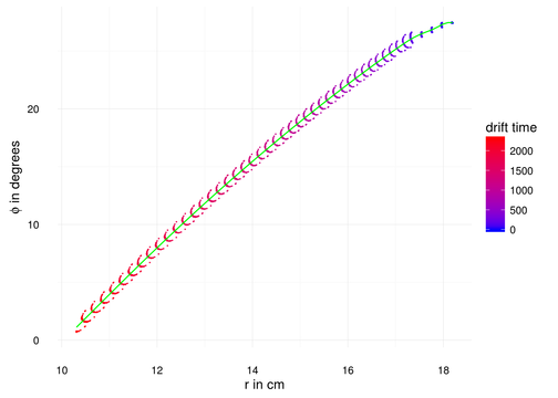
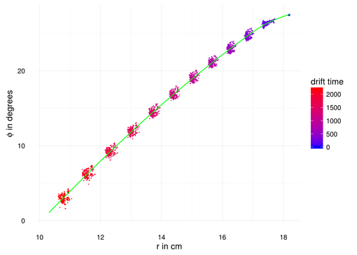
A given spacepoint (in r-φ) is only determined by an anode index and an arrival time. Because there is a whole group of different driftlines that end on the same anode (see Figure 4) a whole range of spacepoints share these characteristics. Figure 9 shows the distribution of such groups of isochronous points in the absence of diffusion. The limit on r from this effect alone is around 2 mm. Originally, we thought some of the crescent-shape structure of these groups could be used to improve this resolution, but diffusion completely washes out the shape, as is shown in Figure 10. The inclusion of diffusion in this simulation is only approximate, so the results should not be taken too quantitatively, but it can be assumed that a reasonable estimate for the r-φ spacepoint resolution is 2-5 mm.
Figure 9 - Isochrones, i.e. groups of spacepoints of equal drift time (separation of groups is 50ns)
Figure 10 - Isochrones under the influence of diffusion (separation of groups is 200ns)
Self-Calibration from Cosmic Data
Instead of relying on Garfield, it is possible to use basic assumptions about cosmic ray tracks to generate a space-time relation from real data. The assumptions, which do not hold for all cosmic tracks, but should apply to a majority, are as follows:
- Cosmic tracks are straight lines within the detector volume (most cosmic muons don’t experience large-angle scattering inside the detector)
- Cosmic rays enter and leave the detector volume through the sides of the cylinder, i.e. passing by anode wires (this applies for a horizontally mounted TPC like the prototype but even for a vertical geometry such tracks are available)
- Ionization from these close passes to anode wires will produce the first signals of a given event, these signals arrive at the entrance and exit wire at approximately the same time.
From these assumptions, the space-time relation can be produced in the following way, only shown for zero magnetic fields, but with some extra care this can be done in the presence of a magnetic field as well:
- Select only events with coincident first signals in two well-separated (groups of) anodes
- Construct a straight line between those anodes (using the weighted mean of a group for increased accuracy)
- For each anode signal falling between entrance and exit anode, determine the intersection point of this straight line and the average drift line of an electron reaching the given anode from the cathode
- Record the coordinates of this point relative to the anode position versus the time of the anode signal relative to the time on entrance and exit anode.
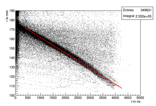
Figure 11 shows an example result of this process in comparison to the Garfield++-derived formula.
With enough statistics, a space-time relation can be extracted e.g. from the peak of the radius distribution for a given drift time, i.e. a slice of the histogram in Figure 9.
Figure 11 - Radius versus drift time determined from the self-calibration method, the red line represents the results from Garfield++.
Pad Matching and Z-Coordinate
In many ways the z-coordinate is the easiest problem to solve, as the magnetic field does not influence the electron drift in this direction. The z-coordinate of the electron origin is therefore the same as that of the electron end point, which is given by the position of the pad detecting the signal. Assembling a full track point is complicated by the fact that pad signals have to be matched to corresponding anode signals by time.
The exact method of matching pads to anodes is still in flux, but we have had success on simulated signals using a relatively simple coarse bin matching. The results presented in section 5.4 are based on this method, in which the pad results are re-binned to the width of a chosen coincidence time (e.g. 20 ns) and a match is found if an anode signal falls within a filled bin of the pad result.
We only recently started producing real pad signals from the prototype and the analysis is ongoing, but since the signals look very clean and similar to the simulated signals it is unlikely there should be complications.
Results
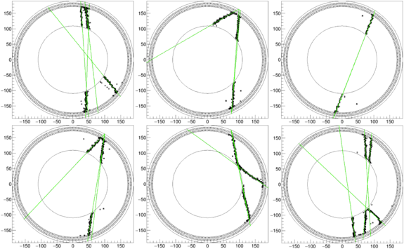
Figure 12 - Reconstruction of cosmic events from the prototype in r-φ projection. Black points are reconstructed space points, green lines are track fits.
Figure 12 shows reconstructed space points in the r-φ projection for six cosmic ray events detected with the rTPC prototype. It includes the result of the track finding algorithm as green lines. Since the algorithm works from large radii inward, any track crossing the entire chamber is reconstructed as two tracks, which should ideally be perfectly collinear. The match between those two lines is an indication of the performance of the detector and reconstruction.
The deconvolution method results in multiple points for any given anode signal, allowing for both the detection of two or three tracks affecting the same wire, as well as a full track spanning the entire radius range from cathode to anode while only affecting three anode wires, seen at in the bottom right of the bottom right event.
Track Fitting and Vertex Finding
The reconstruction program begins by acquiring the anode wire and pad signals from the Geant4 simulation. A routine matches the timing data of the two elements and determines the spacepoints in the chamber.
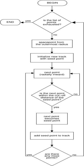
When all the spacepoints are acquired, a pattern recognition algorithm is tasked to sort them into tracks. This track finding algorithm begins from a reconstructed spacepoints at the outermost radius and searches for a neighbouring point at a smaller radius within a given distance cut, until the inner cathode radius is reached. This operation is repeated until all the spacepoints at large radii are exhausted. The algorithm is visualized in the Appendix (Section Error: Reference source not found).
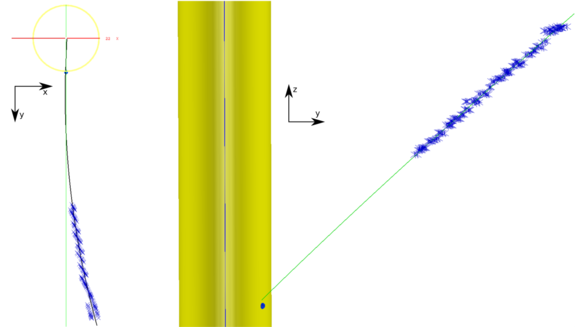
In the presence of a magnetic field, the identified tracks are modeled by a helix, whose parameters are determined by a least-squares minimization. The result of the reconstruction procedure outlined here is shown in Figure 13, which displays two views of the same reconstructed pion trajectory.
Figure 13 - Two orthogonal views of the same pion trajectory in the presence of a magnetic field. The trap volume is shown in yellow.
In order to determine the antihydrogen annihilation location, one more step is necessary, namely finding the point of where two or more reconstructed tracks pass closest to each other. The vertex is determined by minimizing the distance of the pair of helices that pass closest to one another and to a common point. When there are more than two helices, these are added to the minimization to the common point if the final chi-square is less than a cut-off value.
Tracking Results
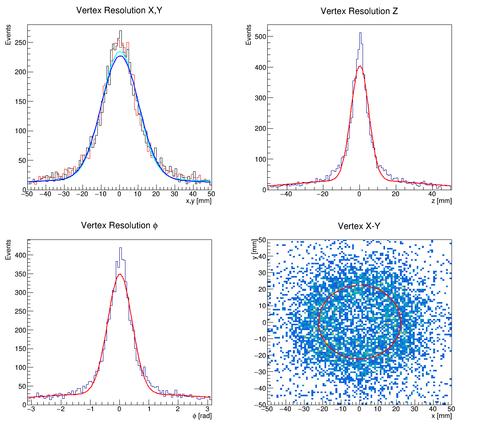
The estimated performance of the tracking and vertexing algorithms, determined from the Monte-Carlo simulation, are reported in the Table below. The efficiency with which the reconstruction procedure finds the annihilation vertex (defined as the ratio of the number of reconstructed vertexes to the number of generated ones) is remarkably high, guaranteeing “high statistics” for the experiment. The vertex resolution, which is visualized in Error: Reference source not found suits the physics goal set by the ALPHA-g experiment.
Space point resolution r-φ 2 mm Space point resolution z 4 mm Average number of space points per track 132 ± 40 Vertex resolution r (9.1 ± 0.1) mm Vertex resolution φ (24.0 ± 0.5)° Vertex resolution z (5.0 ± 0.1) mm Vertex reconstruction efficiency (94.8 ± 0.3) % Average Number of Helices per vertex 3.25 ± 0.01 Figure 14 - Vertex resolution, i.e., the distance between the reconstructed vertex and the one simulated in the Monte Carlo simulation. Bottom right is the distribution of the reconstructed vertexes (coloured) in the x-y plane. The distribution of the generated (Monte Carlo) vertexes is the red ring, corresponding to the trap radius
Prototype Results
The final test of the rTPC prototype instrumented with the 8 anode readout cards and all the 8 pad readout boards consisted in studying the angular and spatial distributions of cosmic ray tracks. Most of the cosmic rays impinging on the detector, due to a single particle (muon) crossing the gas volume, are reconstructed as two tracks. This occurs since the pattern recognition algorithm searches for tracks built from spacepoints whose radial coordinate is not increasing. However, due to orientation of the detector, for many tracks the reconstructed spacepoints first approach the inner cathode and then move away from it as the cosmic ray moves through the gas volume, as shown in Error: Reference source not found.
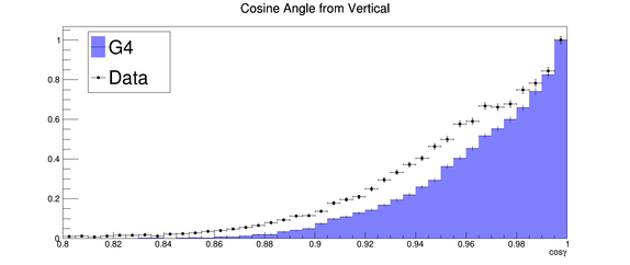 Figure 15 – Distributions of the cosine of the angle formed by reconstructed cosmic rays and the vertical for both simulated (blue) and prototype (black dots) data, only for events consisting of exactly two tracks. Both distributions are normalized to the maximum value.
The angle formed by two tracks due to a single particle is ideally 180º, however the finite resolution of the detector can smear this value. Determining the deviation from this ideal value is a measure of the performance of the prototype and of its analysis package. The results of such analysis are reported in Error: Reference source not found 16
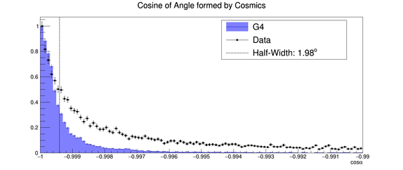 Figure 16 – Distributions of the cosine of the angle formed by reconstructed cosmic rays for both simulated (blue) and prototype (black dots) data. Both distributions are normalized to the maximum value. The dashed line indicates the cosine angle at half the maximum.
The difference between 180º and the value of the angle at which the aforementioned distribution is half of its maximum is less than 2º. The same analysis has been performed on the Monte Carlo data obtained with the same simulation, under the appropriate conditions (magnetic field, gas mixture, orientation), described in Section 5.1. As it can be seen from the figure, there is a good qualitative agreement between the real data and simulation, while the precise value from the simulation is 1.6º.
A related evaluation of the detector performance is performed by determining the distance of closet approach, or DCA, between the two reconstructed tracks that constitute a cosmic ray. Ideally, the two tracks should intersect at one point, i.e., their distance should be zero. Figure 17 shows that the half-width of the distribution of the DCA calculated from the prototype data is 4.4 mm, which is comparable to the spacepoint resolution. The same analysis performed on simulated data yields qualitatively similar results.
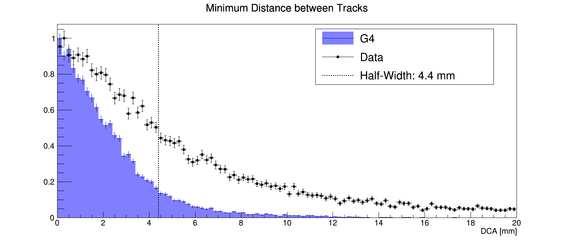 Figure 17 – Distributions of the distance of closest approach (DCA) between two reconstructed cosmic ray tracks for both simulated (blue) and prototype (black dots) data. Both distributions are normalized to the maximum value. The dashed line indicates the DCA at half the maximum.
Future Improvements / To Do
The following items are either in the process of being added/improved or have been added but still require testing:
Improved pad signal deconvolution
The single avalanche response of the pad electronics is not yet fully understood, leading to a less than optimal deconvolution result. It may also be beneficial to investigate a different deconvolution algorithm (Fourier-deconvolution) for the pad signals.
Tuning parameters and algorithms
Both the deconvolution and pad/anode matching have several adjustable parameters. The impact of these needs to be investigated systematically to reach the optimal result.
Reorder deconvolution and matching
In the current process space points are generated from anode signals and pad signals are then used to add the z-dimension, leading to a fundamental asymmetry between anodes and pads. The preferable method is this:
- Generate anode space points from deconvoluted anode signals (r known, φ known, z not well known).
- Generate pad space points from deconvoluted pad signals (r known, φ not well known, z known).
- Match anode and pad space points into combined 3D space points.
("Not well known" refers to the limited z information from anode signal charge division and coarse φ information from the pad column position.)
Include electron positron pair tracks in vertex reconstruction
In addition to pions the TPC will also see electron positron pairs, which can add information to the tracking algorithm. The influence of adding this information is currently under investigation.
Investigation discrepancies the results of the reconstruction of the Monte Carlo and the prototype data
Although the reconstruction of the Monte Carlo agrees qualitatively very well with the analysis of the prototype data, numerical differences are yet to be understood. Two aspects of the simulation are under investigation: the ionization of the gas due to the passage of the charged particles and the generation of the signals on the anodes and the pads with the addition of the noise. Moreover, it is plausible that the current simulation (designed by keeping in mind the full TPC in the ALPHA environment) does not reproduce all the geometric constraints in the prototype setup, therefore the Monte Carlo data must be further processed to find the real experimental conditions.
Simulation developments
As mentioned earlier, the cryostat in the Geant4 simulation is modelled on the current ALPHA-2 apparatus. When the final design of the ALPHA-g cryostat is made available, the full geometry of the apparatus will be imported into the Monte Carlo. The same is true for the internal magnets, whose design is already available, but their support structure is not. Furthermore, the generation of the antihydrogen annihilation positions does not currently follow any particular physical distribution, therefore the actual spatial and temporal annihilation distribution, compatible with the magnets ramp, will be included. A detailed magnetic field map near the edges of the TPC and inside the trapping volume is to be included to take into account all the effects related to field inhomogeneities. Finally, the Geant4 simulation is designed to produce data structures equivalent to the one produced by the DAQ system and, since the latter is in development, the Monte Carlo code will have to closely follow it.
Alternative Track Finding
The current algorithm to identify tracks performs well, as shown in the results section. However, it is conceivable to implement an iterative procedure which, after finding an initial set of spacepoints, attempts to add and/or remove new ones based on some optimal criteria. This is not a crucial development but it can lead to better tracking performance.
Cosmic Rejection
Antihydrogen annihilation identification in ALPHA crucially depends on the software capability to reject background events, i.e., cosmic rays. Given that the ALPHA-g detectors offer more information than what was available in ALPHA, new and more sophisticated algorithms will be developed to remove backgrounds events. Two types of tools will be deployed: “online” software aimed to monitor antihydrogen production and “machine learning algorithms” to eliminate background from the physics measurements.
Appendix
Figure 15 - Flowchart for the track finding algorithm
