Components: Difference between revisions
(Created page with "DUMMY * Description * Reference * Requirement * Prototype * Full rTPC * Power * Signals * Production per * TDE1750 K. Ong ALPHAg (P344); Temperature Monitor Bd Assembly TDE17...") |
No edit summary |
||
| (35 intermediate revisions by the same user not shown) | |||
| Line 1: | Line 1: | ||
Back to [[Alpha-g]] | |||
=='''AWB - ANODE WIRE BOARD'''== | |||
* Description | * Description | ||
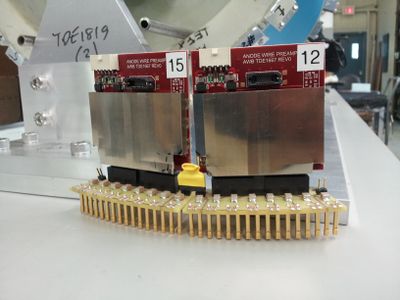
16 channels bi-polar pre-amp used for the Anode wire, mounted on the 2 end plates of the rTPC | |||
[[File:TDE1667.jpg|400px|none|AWB]] | |||
* Reference | * Reference | ||
Schematic_TDE1667.pdf | |||
TDE1668 (Assembly TED1667) | TDE1668 (Assembly TED1667) | ||
* Requirement | * Requirement | ||
Prototype: 16 boards | |||
Full rTPC: 2 x 16 boards (on both endplates) | |||
* Power | * Power | ||
+5V@300mA, -5V@300mA per board | +5V@300mA, -5V@300mA per board | ||
| Line 39: | Line 26: | ||
80.- Assembly based on[EDIT] 15 boards | 80.- Assembly based on[EDIT] 15 boards | ||
128.- parts based on 44 boards | 128.- parts based on 44 boards | ||
=='''AWC - ANODE WIRE CARD'''== | |||
* Description | |||
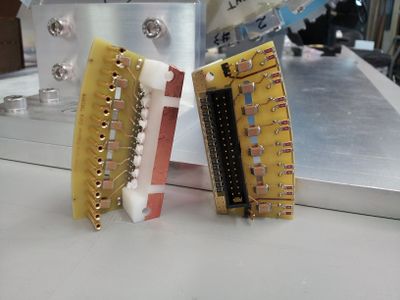
Interface card between the Anode wire crimp pins and the AWB. Mounted on the 2 end plates of the rTPC. | |||
Distribute the HV to 16 anode wires and HV decouple the Anode signal for the pre-amp | |||
[[File:TDE1858.jpg|400px|none|Anode Wire Card]] | |||
* Reference | |||
Media:Schmeatic_TDE1858.pdf | |||
https://edev.triumf.ca/svn/edevel00423 | |||
* Power | |||
HV input through single cable | |||
HV daisy-chained to the neighbor card through 2 pins header x2 | |||
* Requirement | |||
Prototype: 2 x 16 | |||
Full rTPC: 2 x 16 (both end plates) | |||
* Signals | |||
1.44 Mill-Max 8360 (long socket) x16 | |||
3.86 YSS-117-01-S-D x1 | |||
* other components | |||
1.00 HV cap SMD/SMT 1812 1000pF 4KV 20% Tol. X7R x16 | |||
0.20 HV resistor CHV1206-FX-1004ELF 1206 1Meg 1.6kV 1% Tol x32 | |||
0.02 Resistor RMCF1206FT1M00 1206 1Meg 1% Tol x32 | |||
* Production per card | |||
11.- PCB based on 50 cards | |||
100.- Assembly based on 36 cards | |||
50.- Estimated part cost | |||
=='''AWTC - Anode Wire Transition Card'''== | |||
'''Cancelled''' Will be integrated into the new FMC-32 card. | |||
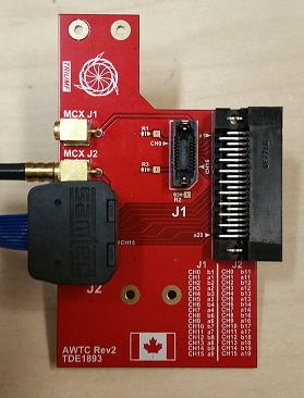
* Description | |||
WFD front transition card for blue cable to the 62.5 Msps WFDs | |||
2 x 16 Anode Wires, 2 MCX Test Signal Inputs | |||
[[File:awtc.jpeg|400px|none|Anode Wire Transition card]] | |||
* Reference | |||
Media:Schematic_TDE1894.pdf | |||
TDE1893 (Assembly TDE1894) | |||
edev link | |||
* Requirement | |||
Prototype: 3 | |||
Full rTPC: 16 cards for Alpha-16 | |||
* Signals | |||
4.40 Connector input: ERF8-010-0.05-S-DV-K-TR x2 based on 40 | |||
6.24 Connector output: FX2-40P-1.27DSL(71) x1 | |||
9.55 Test signal input: J01271A0151 x2 | |||
* Production per card | |||
12.25 PCB based on 30 cards | |||
50.- Assembly | |||
30.- Estimated parts cost | |||
=='''RTM - Barrel Scintillator and Anode wire Transition card'''== | |||
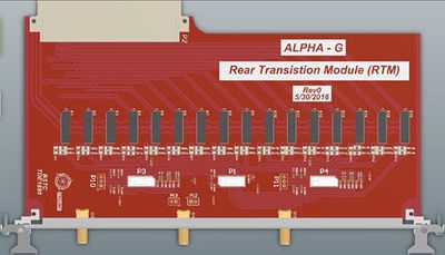
* Description | |||
WFD rear transition card for blue cable to the 100Msps WFDs | |||
Double purpose 1) used for Barrel Scint (2x8 channels) 2) Anode Wires (1x16) | |||
[[File:Rtm.jpeg|400px|none|Barrel Scintillator and Anode wire Transition card]] | |||
* Reference | |||
TDE1895 (Assembly TDE1896) | |||
https://edev.triumf.ca/svn/edevel00423 | |||
* Requirement | |||
Prototype: 4 | |||
Full rTPC: 16 for the barrel scint | |||
* Power | |||
Contains input protection relays (powered by the VME backplane) | |||
* Signals | |||
4.40 Connector input: ERF8-010-0.05-S-DV-K-TR x3 based on 40 | |||
52.00 Connector output: Harting DIN 41612 F 160 POS 2.54mm x1 | |||
* Production per board | |||
27.- PCB based on 30 cards | |||
300.- Assembly based on 5 cards | |||
12.- Front panel based on 30 cards | |||
4. Handles based on 30 pairs | |||
100.- Estimate part total cost | |||
=='''HVRC - High Voltage Resistor card'''== | |||
* Description | |||
[[File:hvrc.jpeg|400px|none|]] | |||
* Reference | |||
High Voltage resistor chain for the endplate rings | |||
* Requirement | |||
Prototype: 2 | |||
Full rTPC: 2 one per endplate | |||
* Production per board | |||
9.4 PCB based on 10 card | |||
100.0 Assembly based on 2 cards | |||
24.0 Part cost | |||
=='''CDM - Clock Distribution Board'''== | |||
* Description | |||
Receive the external reference clock for distribution to the 16 Alpha-16, 8 FEAM, ALPHA-T, TDC, BOBs | |||
Does distribute the Trigger from the Alpha-T to the 16 Alpha-16, 8 FEAM, TDC. | |||
[[File:Cbd.jpeg|400px|none|Clock Distribution Board]] | |||
* Reference | |||
* Requirement | |||
Prototype: 1 | |||
Full rTPC: 1 | |||
* Power | |||
VME power | |||
* Signals | |||
* Production per board | |||
1500.- Module | |||
120.- front panel based on 6 fp | |||
10.- VME handle based on 7 | |||
=='''FMCLink- FMC Gbit link board'''== | |||
* Description | |||
2xQSFP slots. Each QSFP slot supports 4x GigE (or with QSFP+, 4x 10GigE links) | |||
Has 1 eSata for Clock communication to ALPHA-T | |||
[[File:Fmc.jpeg|400px|none|FMC link]] | |||
* Reference | |||
* Requirement | |||
Prototype: 1 | |||
Full rTPC: 10 (2 Trigger board, 8 Padwing board) | |||
* Power | |||
Alpha-16 | |||
* Signals | |||
* Production per board | |||
200.- | |||
=='''ALPHA-16 WFD Board'''== | |||
* Description | |||
16 channels WFD 12bits@105Msps | |||
possible additional 32 channels WFD 12bits@62.5 | |||
[[File:Grif-16.jpeg|400px|none|Grif-16]] | |||
* Reference | |||
* Requirement | |||
Prototype: 11 (available) | |||
Full rTPC: 16 | |||
* Power | |||
VME board | |||
* Signals | |||
* Production per board | |||
3000.- board | |||
135.- front panel based on 5fp | |||
30.- VME ejector based on 10 | |||
=='''FMC32 - FMC 32x62.5Msps board'''== | |||
* Description | |||
32 channels WFD 62.5Msps FMC format for the Alpha-16 | |||
Has 1 Sata for Trigger communication to Alpha-T | |||
[[File:Fmc.jpeg|400px|none|FMC62]] | |||
* Reference | |||
* Requirement | |||
Prototype: 3 | |||
Full rTPC: 8 | |||
* Power | |||
from Alpha-16 | |||
* Signals | |||
Bi-polar input 2Vpk2pk | |||
* Production per board | |||
980.- mezzanine | |||
=='''FEAM - Padwing Board'''== | |||
* Description | |||
Cathode pad readout board for 288 channels, uses the AFTER chip ASIC. | |||
A board composed of 2 wings (2 AFTER per wing) and central acquisition section with optical link output. | |||
Power provided by contact on the back of the padwing card through 3 copper bars. | |||
[[File:PWB.jpg|400px|none|Padwing board]] | |||
* Reference | |||
TDE1653 | |||
* Requirement | |||
Prototype: 8 | |||
Full rTPC: 64 | |||
* Power | |||
+5.2V @ 1700mA | |||
+2.6V @ 750mA | |||
* Signals | |||
11.- Connector to cathode board TFM-125-L2-S-D-K x4 | |||
150.- AFTER chip (Euro 120) based on 360 x4 | |||
* Production per board | |||
440.- PCB based on 10 (190.- based on 70) | |||
200.- Assembly based on Estimation | |||
1000.- Estimated part cost | |||
=='''ALPHA-T - Trigger Board'''== | |||
* Description | |||
Takes 16 LVDS links from the 16 Alpha-16 for Trigger decision. The trigger output is fed to the CDM for distribution to | |||
the 16 Alpha-16, 8 FEAM, TDC, and other. | |||
[[File:|400px|none|]] | |||
* Reference | |||
* Requirement | |||
Prototype: 1 | |||
Full rTPC: 1 | |||
* Power | |||
VME | |||
* Signals | |||
* Production per board | |||
=='''PDB - Power Distribution and monitoring board'''== | |||
* Description | |||
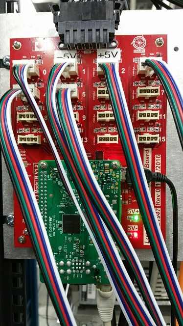
16 channels 2 voltage distribution board for AWB and BSB. | |||
Measures 32 individual DC current and input voltage for 16 power cable to the AWB or BSB. | |||
Uses a RaspberryPi card for the network interface. Input voltage range determined by a selection of divider resistors. | |||
Onboard temperature sensor and access to 3 spare ADC channels for a remote temperature of voltage sensing (+-1.65V). | |||
[[File:Pdb.jpeg|400px|none|Power Distribution board]] | |||
* Reference | |||
edev link | |||
Media:Schematic.pdf | |||
TDE1947 K. Ong ALPHAg (Pxxx); Power Distribution & Monitor Bd Assembly | |||
TDE1946 K. Ong ALPHAg (Pxxx); Power Distribution & Monitor Bd | |||
* Requirement | |||
Prototype: 2 | |||
Full rTPC: 4 | |||
* Power | |||
TP-Link UH720 USB Hub for onboard Raspberry Pi, PL512 for main power | |||
* Signals | |||
16 dual input voltage. Access to 4 spare ADC input channels (Up to +-1.65V) for remote voltage/temperature sensing. | |||
Power Output x16: IPL1-105-01-F-S-K | |||
Power Input x1: MPT-06-01-01-L-RA-SD | |||
Raspberry Pi: Ethernet | |||
* Production per board | |||
$47.00 - PCB Manufacturing (based on order of 8) | |||
$49.00 - Raspberry Pi | |||
$65.00 - ICs, Passives and misc Electronics. | |||
$105.00- Connectors and Cables. | |||
=='''CPWC - Cathode Pad Wall card'''== | |||
* Description | |||
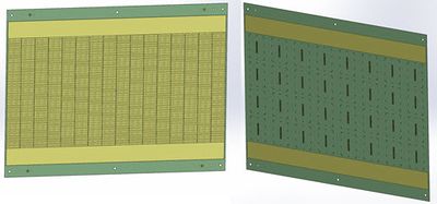
Half cylindrical FR4 curved PCB board making the Cathode pad rTPC outer wall | |||
Composed of 1152 pads connected to 16 AFTER chip (72). | |||
[[File:Cpb.jpeg|400px|none|Cathode pad card]] | |||
* Reference | |||
TDE1663 (Assembly TDE1664) | |||
* Requirement | |||
Prototype: 2 | |||
Full rTPC: 16 | |||
* Signals | |||
12.- Connector on cathode board SFM-125-22-S-D-K (mating with TFM-125-L2-S-D-K on PADWing) x32 | |||
* Production per board | |||
630.- PCB based on 6 cards | |||
800.- Resistors assembly based on 2 card | |||
700.- Stencils based on 2 | |||
384.- Connector based on 70 | |||
'''DUMMY''' | |||
* Description | |||
[[File:|400px|none|]] | |||
* Reference | |||
* Requirement | |||
Prototype: | |||
Full rTPC: | |||
* Power | |||
* Signals | |||
* Production per board | |||
'''DUMMY''' | |||
* Description | |||
[[File:|400px|none|]] | |||
* Reference | |||
* Requirement | |||
Prototype: | |||
Full rTPC: | |||
* Power | |||
* Signals | |||
* Production per board | |||
'''DUMMY''' | |||
* Description | |||
[[File:|400px|none|]] | |||
* Reference | |||
* Requirement | |||
Prototype: | |||
Full rTPC: | |||
* Power | |||
* Signals | |||
* Production per board | |||
'''DUMMY''' | |||
* Description | |||
[[File:|400px|none|]] | |||
* Reference | |||
* Requirement | |||
Prototype: | |||
Full rTPC: | |||
* Power | |||
* Signals | |||
* Production per board | |||
'''DUMMY''' | |||
* Description | |||
[[File:|400px|none|]] | |||
* Reference | |||
* Requirement | |||
Prototype: | |||
Full rTPC: | |||
* Power | |||
* Signals | |||
* Production per board | |||
'''DUMMY''' | |||
* Description | |||
[[File:|400px|none|]] | |||
* Reference | |||
* Requirement | |||
Prototype: | |||
Full rTPC: | |||
* Power | |||
* Signals | |||
* Production per board | |||
Latest revision as of 05:00, 25 September 2017
Back to Alpha-g
AWB - ANODE WIRE BOARD
- Description
16 channels bi-polar pre-amp used for the Anode wire, mounted on the 2 end plates of the rTPC
- Reference
Schematic_TDE1667.pdf
TDE1668 (Assembly TED1667)
- Requirement
Prototype: 16 boards
Full rTPC: 2 x 16 boards (on both endplates)
- Power
+5V@300mA, -5V@300mA per board
1.60 Connector: IPL1-105-01-F-S-RA-K (Terminal) / IPD1-05-S-K (Socket)
- Signals
8.78 Connector input: SSQ-117-02-G-D (Socket) / TSS-117-01-S-D (TDE 1858) x1
4.40 Connector output: ERF8-010-05.0-L-DV-L-K-TR / ERCD (cable assembly) x1
- Production per board
 45.- PCB based on 20 boards
 80.- Assembly based on[EDIT] 15 boards
128.- parts based on 44 boards
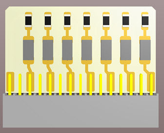
AWC - ANODE WIRE CARD
- Description
Interface card between the Anode wire crimp pins and the AWB. Mounted on the 2 end plates of the rTPC.
Distribute the HV to 16 anode wires and HV decouple the Anode signal for the pre-amp
- Reference
Media:Schmeatic_TDE1858.pdf
https://edev.triumf.ca/svn/edevel00423
- Power
HV input through single cable
HV daisy-chained to the neighbor card through 2 pins header x2
- Requirement
Prototype: 2 x 16
Full rTPC: 2 x 16 (both end plates)
- Signals
1.44 Mill-Max 8360 (long socket) x16
3.86 YSS-117-01-S-D x1
- other components
1.00 HV cap  SMD/SMT 1812 1000pF 4KV 20% Tol. X7R x16
0.20 HV resistor CHV1206-FX-1004ELF 1206 1Meg 1.6kV 1% Tol x32
0.02 Resistor RMCF1206FT1M00 1206 1Meg 1% Tol x32
- Production per card
 11.- PCB based on 50 cards
100.- Assembly based on 36 cards
 50.- Estimated part cost
AWTC - Anode Wire Transition Card
Cancelled Will be integrated into the new FMC-32 card.
- Description
WFD front transition card for blue cable to the 62.5 Msps WFDs 2 x 16 Anode Wires, 2 MCX Test Signal Inputs
- Reference
Media:Schematic_TDE1894.pdf
TDE1893 (Assembly TDE1894)
edev link
- Requirement
Prototype: 3
Full rTPC: 16 cards for Alpha-16
- Signals
4.40 Connector input: ERF8-010-0.05-S-DV-K-TR x2 based on 40
6.24 Connector output: FX2-40P-1.27DSL(71) x1
9.55 Test signal input: J01271A0151 x2
- Production per card
12.25 PCB based on 30 cards
50.- Assembly
30.- Estimated parts cost
RTM - Barrel Scintillator and Anode wire Transition card
- Description
WFD rear transition card for blue cable to the 100Msps WFDs Double purpose 1) used for Barrel Scint (2x8 channels) 2) Anode Wires (1x16)
- Reference
TDE1895 (Assembly TDE1896)
https://edev.triumf.ca/svn/edevel00423
- Requirement
Prototype: 4
Full rTPC: 16 for the barrel scint
* Power
Contains input protection relays (powered by the VME backplane)
- Signals
 4.40 Connector input: ERF8-010-0.05-S-DV-K-TR x3 based on 40
52.00 Connector output: Harting DIN 41612 F 160 POS 2.54mm x1
- Production per board
 27.- PCB based on 30 cards
300.- Assembly based on 5 cards
 12.- Front panel based on 30 cards
  4.   Handles based on 30 pairs
100.- Estimate part total cost
HVRC - High Voltage Resistor card
- Description
- Reference
High Voltage resistor chain for the endplate rings
- Requirement
Prototype: 2
Full rTPC: 2 one per endplate
- Production per board
  9.4  PCB based on 10 card
100.0 Assembly based on 2 cards
 24.0 Part cost
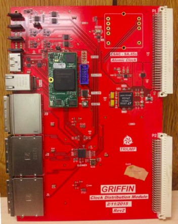
CDM - Clock Distribution Board
- Description
Receive the external reference clock for distribution to the 16 Alpha-16, 8 FEAM, ALPHA-T, TDC, BOBs Does distribute the Trigger from the Alpha-T to the 16 Alpha-16, 8 FEAM, TDC.
- Reference
- Requirement
Prototype: 1
Full rTPC: 1
- Power
VME power
- Signals
- Production per board
1500.- Module
 120.- front panel based on 6 fp
  10.- VME handle based on 7
FMCLink- FMC Gbit link board
- Description
2xQSFP slots. Each QSFP slot supports 4x GigE (or with QSFP+, 4x 10GigE links) Has 1 eSata for Clock communication to ALPHA-T
- Reference
- Requirement
Prototype: 1
Full rTPC: 10 (2 Trigger board, 8 Padwing board)
- Power
Alpha-16
- Signals
- Production per board
200.-
ALPHA-16 WFD Board
- Description
16 channels WFD 12bits@105Msps possible additional 32 channels WFD 12bits@62.5
- Reference
- Requirement
Prototype: 11 (available)
Full rTPC: 16
- Power
VME board
- Signals
- Production per board
3000.- board
 135.- front panel  based on 5fp
  30.- VME ejector based on 10
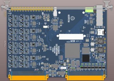
FMC32 - FMC 32x62.5Msps board
- Description
32 channels WFD 62.5Msps FMC format for the Alpha-16 Has 1 Sata for Trigger communication to Alpha-T
- Reference
- Requirement
Prototype: 3
Full rTPC: 8
- Power
from Alpha-16
- Signals
Bi-polar input 2Vpk2pk
- Production per board
980.- mezzanine
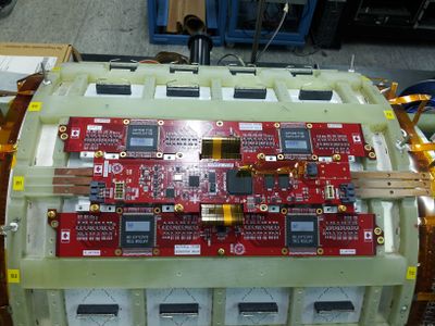
FEAM - Padwing Board
- Description
Cathode pad readout board for 288 channels, uses the AFTER chip ASIC. A board composed of 2 wings (2 AFTER per wing) and central acquisition section with optical link output. Power provided by contact on the back of the padwing card through 3 copper bars.
- Reference
TDE1653
- Requirement
Prototype: 8
Full rTPC: 64
- Power
+5.2V @ 1700mA
+2.6V @ 750mA
- Signals
 11.- Connector to cathode board TFM-125-L2-S-D-K x4
150.- AFTER chip (Euro 120) based on 360 x4
- Production per board
 440.- PCB based on 10  (190.- based on 70)
 200.- Assembly based on Estimation
1000.- Estimated part cost
ALPHA-T - Trigger Board
- Description
Takes 16 LVDS links from the 16 Alpha-16 for Trigger decision. The trigger output is fed to the CDM for distribution to the 16 Alpha-16, 8 FEAM, TDC, and other. [[File:|400px|none|]]
- Reference
- Requirement
Prototype: 1
Full rTPC: 1
- Power
VME
- Signals
- Production per board
PDB - Power Distribution and monitoring board
- Description
16 channels 2 voltage distribution board for AWB and BSB. Measures 32 individual DC current and input voltage for 16 power cable to the AWB or BSB. Uses a RaspberryPi card for the network interface. Input voltage range determined by a selection of divider resistors. Onboard temperature sensor and access to 3 spare ADC channels for a remote temperature of voltage sensing (+-1.65V).
- Reference
edev link
Media:Schematic.pdf
TDE1947 	K. Ong 	ALPHAg (Pxxx); Power Distribution & Monitor Bd Assembly
TDE1946 	K. Ong 	ALPHAg (Pxxx); Power Distribution & Monitor Bd
- Requirement
Prototype: 2
Full rTPC: 4
- Power
TP-Link UH720 USB Hub for onboard Raspberry Pi, PL512 for main power
- Signals
16 dual input voltage.  Access to 4 spare ADC input channels (Up to +-1.65V) for remote voltage/temperature sensing.
Power Output x16: IPL1-105-01-F-S-K
Power Input x1:   MPT-06-01-01-L-RA-SD
Raspberry Pi: Ethernet
- Production per board
 $47.00 - PCB Manufacturing (based on order of 8)
 $49.00 - Raspberry Pi
 $65.00 - ICs, Passives and misc Electronics.
$105.00- Connectors and Cables.
CPWC - Cathode Pad Wall card
- Description
Half cylindrical FR4 curved PCB board making the Cathode pad rTPC outer wall Composed of 1152 pads connected to 16 AFTER chip (72).
- Reference
TDE1663 (Assembly TDE1664)
- Requirement
Prototype: 2
Full rTPC: 16
- Signals
12.- Connector on cathode board SFM-125-22-S-D-K (mating with TFM-125-L2-S-D-K on PADWing) x32
- Production per board
630.- PCB based on 6 cards
800.- Resistors assembly based on 2 card
700.- Stencils based on 2
384.- Connector based on 70
DUMMY
- Description
[[File:|400px|none|]]
- Reference
- Requirement
Prototype:
Full rTPC:
- Power
- Signals
- Production per board
DUMMY
- Description
[[File:|400px|none|]]
- Reference
- Requirement
Prototype:
Full rTPC:
- Power
- Signals
- Production per board
DUMMY
- Description
[[File:|400px|none|]]
- Reference
- Requirement
Prototype:
Full rTPC:
- Power
- Signals
- Production per board
DUMMY
- Description
[[File:|400px|none|]]
- Reference
- Requirement
Prototype:
Full rTPC:
- Power
- Signals
- Production per board
DUMMY
- Description
[[File:|400px|none|]]
- Reference
- Requirement
Prototype:
Full rTPC:
- Power
- Signals
- Production per board
DUMMY
- Description
[[File:|400px|none|]]
- Reference
- Requirement
Prototype:
Full rTPC:
- Power
- Signals
- Production per board
