DarkSide
DarkSide DAQ
The DarkSide-20k data acquisition is to operate in a triggerless mode. This means that every photodetection unit (PDU) produces a data flow independently from its neighbours and no global decision is invoked for requesting data. Also, the experiment is composed of several thousand channels that need to be processed together in order to apply data filtering and/or data reduction before the final data recording to a storage device. The analysis time for a such large number of channels requires substantial computer processing power. The Time Slice concept is to divide the acquisition time into segments and submit them individually to a pool of Time Slice Processors (TSP). Based on the duration of the time segment, the analysis performance, and the processing power of the TSPs, an adequate number of them will be able to handle the continuous data stream from all the detectors.
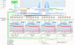
THIS FIG shows the overall DarkSide-20K DAQ architecture. At the bottom, a global Clock is distributed to four waveform digitizers located on the top of the detector. The readout of those WFDs is done by a collection of frontend processors (FEPs) which in turn connect in turn to a second cluster of processors (TSPs, see below).
The Time Slice concept is to segment the data-taking period across all the acquisition modules. The collected data for each segment is then presented to a TSP for processing. Once the analysis is complete, the TSP informs an independent application of its availability to process a new Time Slice.
Physics events happening across two consecutive Time slices is to be managed properly as the TSPs will not have access to the previous time slice. This is addressed by duplicating a fraction of the time slice to the next TSP. This overlapping time is to ensure that this extended segment covers the possible boundary events. It corresponds in our case to the maximum electron drift time within the TPC (∼5ms). The default time slice duration is 1 second, meaning that we will have 0.5% duplicate analyzed events in that overlap window.
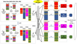
THIS FIG shows the run time segmentation (abscissa). Each segment is processed by a different TSP. The total number of TSPs must be greater than the average time (in seconds) it takes to process 1 second of data. The large number of PDUs (Photo Detector Units, ie. frontend electronics) or channels implies that multiple digitizers are at work. Therefore the time segmentation mechanism requires the transmission of a Time Slice Marker (TSM) to all the digitizers in order to ensure a proper segment assembly based on the Time Slice number. The readout of the individual waveform digitizer (WFD) is performed by a dedicated processor Front-End Processor (FEP). For similar processing power issues as for the TSPs, the FEP will handle a subset of WFDs (2), meaning that in our case, 24 FEPs will collect all the digitizer data. Each FEP will have to read out, filter, and assemble the data fragments from the WFDs covering the predefined time slice duration.
The management of the transmission of the data segment to individual TSPs is left to the Pool Manager (PM) application. Its role is to receive ”idle” notification from any TSPs (once the previous time slice analysis has been completed) and broadcast to all the FEPs the destination address for the upcoming segment to the next available idle TSP.
In order to ensure a proper Time Slice synchronization, a "Time Slice Marker" (TSM) is inserted at the WFDs level under the form of a bit. The frequency of the TSM defines the Time Slice Duration. For each TSM trigger, a WFD event is always produced and therefore will appear in the data stream at the FEP collector. The TSM event is shown in the figure below in orange. While the WFD acquisition is asynchronous due to the randomness of the event generation at the WFD level, the TSM is meant to sort the data across a given FEP based on the Time Slice number. An extra intermediate stage of data filtering or data reduction can be implemented between the Acquisition thread and the sorting thread. The Time Slice sorted output data buffer combining all the WFD of this FEP is then available to the Transfer thread pushing the requested Time Slice data to the Time Slice Processor.
Links
- https://owl.phy.queensu.ca/DS20k/TWiki/bin/view/Main/DaqPage
- https://dsvslice.triumf.ca
- DS-DM VME DS-DM board DarkSide GDM and CDM
- https://daq00.triumf.ca/elog-ds/DS-DAQ/
Dsvslice ver 1
- main computer: dsvslice
- network 142.90.x.x - connection to TRIUMF
- network 192.168.0.x - 1gige VX network
- vx01..vx04, gdm, cdm, vmeps01, etc
- network 192.168.1.x - 10gige DSFE and DSTS network
- dsfe01..04 - frontend processors
- dsts01..05 - timeslice processors
Dsvslice ver 2
Second implementation of the vertical slice is intended to be as close as possible to the final network topology shown on the chart above.
Computer interfaces
- main computer: dasdaqgw.triumf.ca, network links:
- eno1: 1gige RJ45: TRIUMF
- 1gige RJ45 (final: 10gige SFP DAC) to DAQ infrastructure network "green switch"
- enp1s0f0: 10gige SFP: FEP network
- enp1s0f0: 10gige SFP: TSP network
- FEP computer, network links:
- enp1s0f0: 10gige SFP: FEP network, nfsroot to dsdaqgw
- enp1s0f1: 10gige SFP: VX network, dhcp (dnsmasq) for VX modules.
- eno1: 1gige RJ45: not used
- eno2: 1gige RJ45: not used
- TSP computer, network links:
- 10gige SFP: TSP network
Networks
- network 192.168.2.x is the DAQ infrastructure network
- dhcp/dns/ntp from dsdaqgw
- "green switch" central DAQ infrastructure
- 10gige DAC uplink to dsdaqgw
- 1gige RJ45 to juniper-private management interface
- 10gige fiber to per-rack "orange switch" (4x)
- per-rack "orange switch" (4x)
- RJ45 GDM (only in one rack)
- RJ45 CDM (2x per rack)
- RJ45 SCP (slow control PC)
- RJ45 CDU
- RJ45 VME P.S.
- RJ45 "gray switch" management interface
- total: 7 RJ45 ports + 1 SFP fiber uplink
- network 192.168.3.x is the VX network:
- isolated - no connection to dsdaqgw
- dhcp from dsfeNN machine 192.168.3.1
- "gray switch" management from fep machines
- 4x, one "gray switch" per quadrant rack
- 4x "green vx", 1/10gige DAC
- 9x "red vx", 1/10gige DAC
- 6x 10gige fiber to fep machines
- total: 19 SFP ports
- network 192.168.2.x is the FEP network
- dhcp/dns/ntp from dsvslice
- "orange switch" management via dsvslice connection
- 10gige SFP to the dsvslice
- 4x6 = 24x RJ45 to FEPs
- network 192.168.3.x is the TSP network
- dhcp/dns/ntp from dsvslice
- "blue switch" management via dsvslice connection
- 1x 10gige DAC from dsvslice
- 4x6 = 24x 10gige DAC from FEPs
- ? = ?x 10gige DAC from TSPs
- 1x 10gige fiber SFP to external network
- total: 26x + ?x 10gige SFP


