Water cooling system
Introduction
The Cathode pads covering the inner surface of the rTPC are readout with 64 Padwing readout cards (PWB). This electronics is cooled down by a close-loop of a negative pressured water system.
The water circulation system cycles water to shed heat from the data acquisition electronics incorporated into the Time Projection Chamber (TPC) surrounding the anti-hydrogen trap of the ALPHA-g experiment. The water temperature is maintained by contact via a Heat Exchanger with CERN's cooling water supply. The system is designed to maintain a sub-atmospheric pressure in the coolant loop through the detector, to minimize the possibility of coolant water spilling into the detector electronics hidden within the layers of the experimental apparatus. Any small breach of the coolant plumbing would only cause air to bleed into the coolant, rather than liquid leaking out.
Components and Principle of Operation
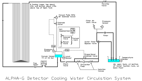
Principle of Operation: during operation, the Pressure PID (proportional/integral/differential controller), PID2, monitors the air pressure in the Vacuum Vessel. When the pressure rises above \~37 mbar it activates the aspirator vacuum pump to bring the pressure down, to maintain an long time averaged pressure of \~340 mbar. This vacuum is then used to draw water from the source Open Tank through the detector cooling lines and then the Heat Exchanger, into the vessel. The Vacuum Vessel's water level is monitored by PID1, using a differential pressure transducer measuring the difference between the air pressure in the top of the vessel and the water pressure at the bottom of the vessel, due to the height of the water. PID1 provides a variable signal to the Proportional Solenoid Valve which varies the fraction of flow recirculating in the short loop path around the Water Pump, which pumps at a constant rate, and thus the quantity of water pulled from the Vacuum Vessel to keep the water level in the vessel constant despite water being constantly drawn in by the vacuum. The water pulled from the Vacuum Vessel is pushed by the pump through the water filter and into the Open Tank, completing the circulation. The rate that water flows through the vessel can be determined by many obstacles in the loop, but ideally it should be dominated by the position of the main Throttle Valve. Other valves should generally be set either fully open or fully closed. The flow rate is monitored by the Flow Meter, whose output is sent to the experiment's DAQ system.
Currently, the system uses deionized water, and relies on a small ribbon of silver metal to provide biocidal activity. The wetted surfaces are mainly plastic and brass, except for the stainless heat exchanger, and the copper cooling tubes in the detector, so it is hoped that ionic corrosion activity will be at a minimum, but time will reveal if a corrosion inhibitor is required.
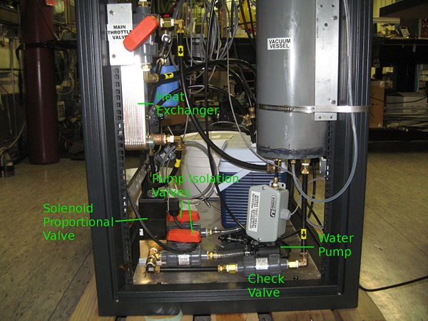
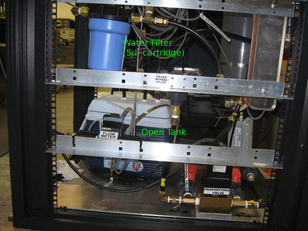
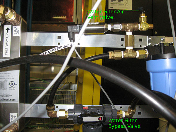
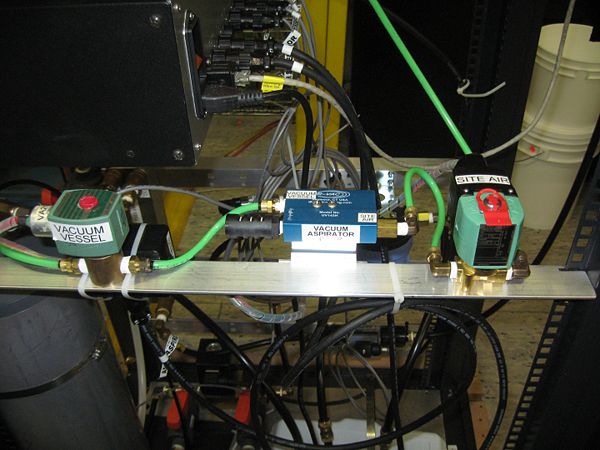
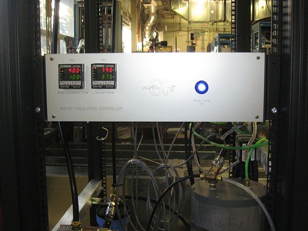
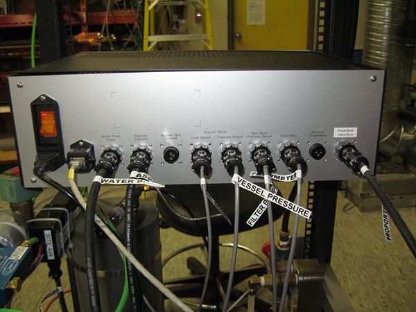
Brief Illustration of Some Components: here is a series of photos of the system during testing, identifying some of the parts indicated in the diagram above; green labels added for components not obviously labelled:
The Vacuum Vessel has a 6.7l capacity, while the Open Tank can hold 16l. A length of transparent teflon tubing is provided at the input to the Vacuum Vessel, and also linking from the bottom of the vessel to the top; the first provides a visual indication of flow, as the low pressure at the entrance to the vessel will cause vapour bubbles to appear in the liquid there, and the second provides a visual indication of the fluid height in the vessel.
The Vacuum Pump is an air driven aspirator, consisting of a dual venturi aluminum block with no moving parts. The aspirator is operated by simultaneous opening of two normally closed solenoid valves, one to site air, and the other to the Vacuum Vessel. With TRIUMF \~100psi site air, it can drive the Vacuum Vessel down to operating pressure of 0.34 bar from atmosphere in under 15 seconds. In usual operation, the pump is triggered when the pressure rises to over \~0.37 bar, and the vessel is partly filled with water, so the pump runs for a much shorter time. (In development testing, the pump was triggered about every eight to twelve minutes during operation. It is expected that a reduced number of tubing connections in the final configuration due to monolithic manifolds delivering flow to the detector loops will result in a lower air in-leak rate, and thus less frequent triggering of the aspirator.)
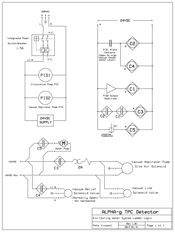
The system is controlled by electronics housed in a 19" rack mount Circulation Control Box. The box has a main AC power switch on the back, which powers the PIDs and a 24VDC power supply. The Water Pump, which runs on 24VDC, has a pushbutton ON switch on the front panel. The two Omega PID controllers PID1 and PID2 have configurable displays, and are addressable by four membrane switches along the bottom.
Operation
Startup for Normal Operation
Before undertaking a startup, read through the complete procedure, and ensure that you have located and correctly identified all the controls mentioned in the process.
This procedure assumes the initial condition has deionized water present in the Open Tank, as well as in the circulation system. It also assumes the system is fully assembled, plumbed and connected. If this is not the case, refer to [Initial Setup Connections](#1A_Initial_Setup_Connections).
1) Starting from a full power down condition, first check that power is switched off at both the Control Box and the Water Pump ON Pushbutton (in Off condition, the button protrudes slightly more). Ensure that the Throttle Valve is fully closed (handle perpendicular to flow).
2) Next, turn on the Circulation Control Box power switch, located on the back of the box. This should cause the two PIDs' numeric LED displays to light with the text "SELF TEST", after a brief delay. After a second or so, the displays will change, and simultaneously the site air solenoid may activate, starting the Aspirator Vacuum Pump, to achieve the necessary vacuum in the Vacuum Vessel. During the period the aspirator is running, the right hand PID - PID2 - will display in its upper (red) line either a blinking "OFL", if the initial pressure is above 800mbar, or a number related to the Vacuum Vessel pressure in millibars, but offset upward by 40 or so. (The lower (green) display shows the target pressure +40mbar. Once the solenoid has switched off site air, the PID2 display upper line should display a number quite close to the vessel pressure in mbar, initially around 330.) Currently the target value (lower, in green) is set to 375.
3) Ensure that the left hand PID, PID1 "Circulation Water Pump", is displaying the appropriate target number (currently this is 150) in green in its lower display. If it is not, press the Index button on the bottom left of the PID. The display should change to a number in red on the upper display, and "SP1" in green on the lower display. Use the up arrow button (and the down arrow if you overshoot) to raise the value displayed in the upper row to 150. Then press the Enter button, and then the Index button once more. The display should change to showing a number in red in the upper row, and 150 in green in the lower row.
4) Next, open the Throttle Valve, a bit under half way (45º). This may be done while the aspirator is running. You may see water rising in the transparent indicator tubing running up the side of the Vacuum Vessel. Currently, the water pump cannot keep up with coolant flow (drawn by the vacuum) if the Throttle Valve is open beyond 45º, and thus the flow will not stabilize but go into a minutes long oscillation.
Fairly promptly after opening the Throttle Valve, when there is water showing at a height in the indicator tubing corresponding to about 1/5 the height of the Vacuum Vessel, press the blue "ON" pushbutton on the Control Box to start the Water Pump; the pushbutton should light up bright blue. Although this pump is powered by 24VDC, you will hear a steady loud hum at around 60Hz when the pump starts running. The left hand PID - PID1 - will display in its upper (red) line a value related to the height of the water in the Vacuum Vessel, in mm, measured from the middle of the grey pressure transducer hanging below the vessel. (This is actually a measure of differential pressure between the weight of water at the bottom of the vessel and the partial vacuum above the water. It is given in arbitrary units, and is not really linearly related to the height of the water column, because the varying low pressure causes vapour bubbles of varying size to appear in the tubing leading to the pressure transducer, which change the effective weight and thus pressure of the water column. However, the relationship wanders only slowly, within a limited range, and as it remains monotonic, it suffices as a PID input for keeping the vessel water level in a fairly steady middling height, which is all the system requires. In operation, the water height will stabilize at a point somewhere in the range of 100 to 180mm, depending on the amount of vapour trapped in the tubing. A bubble may occasionally escape the tube, causing a small abrupt change in the equilibrium level, of a cm or two. This has no impact on system operation.) The upper red (current) number will converge on the lower green (target) value slowly over three to seven minutes or so. Currently the target value (lower, in green) is set to 150. coolant
5) Adjust the position of the Throttle Valve as necessary for the desired flow rate. The rate can be read from the experiment data system (details not yet available).
Shutdown from Normal Operation
Assuming that the system will be simply powered down, with coolant remaining in the system, all that is required to power down is:
1) Close the Throttle Valve.
2) Press the blue "ON" pushbutton on the Control Box to stop the water pump - the blue light will extinguish, and the loud hum will stop indicating the pump is off.
3) Switch off the Control Box from the main switch on the back.
NOTE: If the system is to be left off for some time, it is essential that all three of these operations be performed. In the event of system malfunction, there is a remote possibility that not powering off the control box may result in water being sprayed into the room through the aspirator Vacuum Pump. An alternative precaution would be to valve off the external site air supply valve.
Topping up the Open Tank water level
The water level in the Open Tank may decline over time due to evaporation, and exhaustion of water vapour upon operation of the aspirator valve, so it must be occasionally supplemented by additional water. How often this occurs will be a function of the frequency of aspirator activity, which in turn is determined by the rate of the air leak in the system, which will have to be determined after installation. It is hoped this will amount to no more than quarter-annually with the full-time operation.
Small amounts of deionized or distilled water can be poured into the tank. This assumes we are starting from Normal Operation. Deionized or distilled water must be obtained, and care should be taken not to introduce any trace of organic material which might encourage bacterial growth in the water; the containers used should be thoroughly cleaned.. It should be possible to add water to the system while it is running, by opening the lid of the Open Tank a small amount - a couple of inches, so that water can be poured in without the lid lifting so much that the water inlet tubing is lifted above the water surface.
Water should be added to a minimum of around 1/4 of the height of the container. Depending on how frequently this is done, it might require 1 litre, but should never need more than three. The appropriate level of water in the Open Tank with the system in operation must be determined after installation at CERN, as it is not yet certain what length of tubing will be required to reach the detector, and the Open Tank must be able to hold all the water from the system in the event a maintenance issue requires it to be drained. Refer to the Appendix item [Coolant Levels](#Coolant_Levels:) for a more detailed discussion.
Appendix
Initial Setup Connections
Power: The Control Box is equipped with universal AC-capable hardware, which can cope with 90-240VAC, 50 or 60Hz, so it can be run in North America or Europe (or anywhere else). The box has a standard AC modular input, so it requires only a power cord mateable to the local AC socket standard.
Controls: The back of the Circulation Control Box has nine black plastic "CPC" control connector receptacles mounted, plus an RJ45 ethernet connector, in addition to the Power Entry Switch Module. The receptacles, and the cables plugged into them, are each labeled with their function. The cables are also labeled at the far end, corresponding to an approximately matching label on the object they connect to. (A "Vacuum Vent Solenoid" is currently not implemented). All outputs from the box are 24VDC or less.
Plumbing: The plumbing is mostly done in black polyethylene "polyflo"-type tubing, with polyflo connectors, mainly 1/2"OD, with some 3/8 and 1/4. There is one short length of clear, wire-wound PVC 1/2" I.D. hose, and one of 1/4"ID, 1/2" OD tygon tubing, for connecting to the Water Pump, which has hose barb connections - 1/2" in, 1/4" out. For most possible component failures requiring replacements, it won't be necessary to undo the NPT fittings; the plastic valves all use "true union" o-ring connections between the NPT fitting and the valve body, and spare valves will have same connectors, so the NPT section can be left on the tubing.
The Heat Exchanger is to be connected to CERN's cooling water system, via ports labelled Coolant In and Out. These ports are provided with 1/2NPT connections; presumably we will have to provide hose to the CERN system. What connections are used for that may only be determined when we arrive there.
Maintenance Items
Water Filter Change: A pressure gauge is mounted on the filter input to monitor filter back pressure, and if it is found to increase significantly (to a point to be determined), it would indicate that the 5µ filter cartridge should be replaced. We have provided one in the water systems spares. The system is built so the swap can be done while the system is running. First the Water Filter Bypass Valve must be switched. This valve has a non-standard function, so its operation should be understood before use. The valve handle can be rotated 360º, and has a label on it like a "T" with arrows at the tip of each line. These indicate the water flow paths - three directions are connected, and the fourth is blocked. In normal operation, the handle is oriented so the "T" is lying on its side, with its base line pointing (left) toward the tubing running to the Water Filter. Rotating the handle counterclockwise so the base line points down will allow water to flow both through the filter and the bypass line - the valve is "make before break". Continuing to rotate the handle in the same direction will bring the base line to point to the bypass line, and the filter will be bypassed. Although the handle allows full rotation, returning the valve to its original position should be done by reversing the direction of rotation - UNDER NO CIRCUMSTANCES should the valve be rotated so that the base of the "T" points upwards, thus blocking all output from the Water Pump!
Once the flow from the pump is shunted to the bypass line, the Filter Air Vent Valve should be opened, to allow water to drain from the upper portion of the filter into the Open Tank. This will minimize the amount of water spilled when undoing the filter housing body, but won't eliminate spillage entirely, so a mop rag and bucket should be on hand to deal with perhaps half a cup of water. Currently we are not using any additives in the water, it is not toxic, but this may change if we find problems with algae or corrosion (in which case this manual should be updated...).
Normally, filter housings of this type are supplied with a large ring wrench, but it seems for this smallest version it was not deemed necessary, and it has been possible to mount and remove the housing body just using two hands. There is an o-ring at the seal, which should be handled carefully to ensure no grit compromises the seal. Upon removing the filter body, it should be cleaned before the new cartridge element is mounted; then the body should be screwed back together as snug as it was before.
Water Pump Replacement: It is possible that the Water Pump may fail, and we have spares for that eventuality. If the pump fails, water will be pulled into the Vacuum Vessel raising its water level, but the control system will inhibit the Vacuum Pump, so water will not escape via the aspirator. Consequently, the pressure of air above the water in the vessel will rise to atmosphere, and flow will stop. Detector cooling will be compromised, and thus detector electronics should be powered down, but there will be no other consequences within the water system; the system may then be turned off, and the pump replaced.
Obviously if the Water Pump is in need of replacement, the system power must be off. The Water Pump is mounted with Isolation Valves. When the valves are closed, the "true union" connections can be unscrewed from the valve body, and the pump, connected hoses and NPT fittings can be lifted away, with relatively minimal water spillage, though about a cup of water may be present in the pump and attached hoses, so ends should be rotated upward when free to minimize spillage, and a mop cloth will be required. This must be done carefully, as the plastic valves can be broken if they are torqued against the fixed plumbing at their Solenoid Proportional Valve end - keep the valves in their fixed orientation while unscrewing the "true union" connections. The "true union" connections employ an o-ring seal; the o-ring is somewhat captive on the valve body, but care must be taken to avoid damage to the surface of the o-ring or its mating surface on the NPT end, and keep them clean, in the usual manner for o-rings, so that upon re-assembly they will make a reliable seal.
Then the hose barb gear clamp connections at the problem pump can be removed and swapped to the spare pump, and reattached to the valves. If it seems practical, a bit of deionized or distilled water could be poured into the hose on the input of the new pump, to help prime it, before reconnecting the valves. The pump will not operate without fluid in the body, and trying to run it in that state will rapidly damage it. However, when it has been connected, and the isolation valves are opened, water should flow into it from the Vacuum Vessel due to gravity.
Coolant Levels
When coolant is fully distributed through the system, the 16 litre Open Tank should be about 1/4 full, but the actual allowable range must be determined after installation at CERN, as it will depend on the distance from the water system rack to the detector, and the amount of water contained in the tubing - the tank must always contain a minimum fluid level to keep the syphoning tube submerged, and must also be able to hold all the water in the system to allow draining. These conditions constrain the tank fluid level for the system when in operation. With the 16 litre Open Tank, it should be possible to maintain a fairly large minimum water level in the tank and still have room to drain the system, thus increasing the length of time before loss of vapour via aspirator operation requires topping up the tank.
Note that in operation, the system can depart from equilibrium when, due to the low pressure at the input of the Water Pump, occasionally vapour bubbles are temporarily caught at the input to the pump, stalling its throughput. When this happens, water continues to flow into the Vacuum Vessel, raising its fluid level from the currently set operation level of about 1/5 (ie ~1.3l) to a maximum around 3/5 (4l). At this point, the partial atmosphere above the water in the vessel is compressed so the pressure rises, and this collapses vapour bubbles, allowing the pump to clear the now tiny bubbles and resume pumping. For our present discussion, this means that the Open Tank must be able to lose around 3 litres of fluid from its normal operating level, and still have the syphoning tube submerged. Thus the minimum operating water level in the Open Tank should be around 4 litres. Meanwhile, with the system in normal operating mode, the Vacuum Vessel will have about 1.3l of fluid, the detector will have about 0.5l, the various components of the system rack will have about 0.5l (not counting the body of the water filter, whose water volume will not be drained), and the 1/2" tubing will contain about 74ml per metre. Figuring a comfortable margin would be 14 litres in the 16 litres tank, this should allow for a very comfortable 100m of tubing before overflowing the tank (a problem encountered with the 9.5l tank in the prototype development, and 16m of tubing). Every 13.5m less tubing than this required means a litre that can be safely added to the minimum in the Open Tank, thus extending the time between required additions of more water.
Draining coolant from the system
There may be times when the water in the system must be fully or partly drained, if it is felt it needs replacement, or if the system is to be dismantled; or, the system may have been overfilled and it is desired to reduce the total water in the system. There are a few routes to achieve this.
Reducing the water volume in the system is best achieved by simply popping the lid on the Open Tank up an inch or so, and introducing a (clean!) tube to syphon water from the tank; this can probably be done even when the system is in operation, as long as the minimum level of 4l in the tank is observed.
For the more extensive draining processes, the common point is that water is drained from the tubing by running the system with the input open to air, rather than having the Open Tank water supply connected. This is done by first adjusting the target height of the Water Circulation Pump PID1, to 10, the lowest allowed value, to minimize water held in the vacuum vessel. Then close the Throttle Valve, power off, and disconnect the polyflo connection to the bottom of the valve, from the tubing running from the Open Tank. This tubing will be full of water, and a small amount will be present in the valve body, so a mop rag to catch the water is helpful, and the tubing end should be immediately raised so its water will drain back to the Open Tank.
If it is desired to return the water to the Open Tank, the system can then be run, and the throttle valve opened, which will draw air through the tubing and the detector, pulling down the water level in the Vacuum Vessel and delivering coolant water to the Open Tank where it will accumulate until air reaches the vacuum vessel. This will cause a considerable noise of air entering the vessel, and the vacuum pump will be triggered by the rise in pressure. Leave the system in this condition for a few seconds to flush water from the tubing, then the system should be powered off. The entire process may complete in as little as a minute, depending on the distance from the system rack to the detector.
If it is desired to empty the system completely, including the Open Tank, it may be convenient to disconnect the polyflo union in the tubing running from the Water Filter to the Open Tank, and redirect the flow from the filter to an external container (~14 litre capacity) or a drain. The system is then run as described in the preceding paragraph. After emptying and powering off, the Filter Bypass Valve can be switched to bypass position, the Filter Air Vent Valve opened to drain water from the top of the Water Filter, then the blue Water Filter body can be unscrewed from its top, so it drops free, and the water it contains (perhaps two or three cups surrounding the filter element) can be emptied from the body. Finally the remaining inline tubing unions connecting to the Open Tank can be disconnected, and the tank freed from its gear clamp. The tank lid can then be opened, and the metal biocidal coil strip retrieved, and remaining water in the tank poured out.
Draining the Vacuum Vessel only
It is possible to drain the Vacuum Vessel only, for servicing parts attached to its underside, but this gets complicated, so it may best be left to "an expert". However, in the event that one isn't available, this information is provided; ignore it otherwise.
Draining the Vacuum Vessel alone requires air to be let in to the vessel to replace the water drained, otherwise the Water Pump will pull water out driving the vacuum to a pressure so low (below 300 mbar on the PID2 display) that the water will cavitate at the input of the pump, stalling the extraction, and also potentially damaging the pump.
If there is a substantial air in-leak rate (so that the Aspirator Vacuum Pump is triggered frequently to refresh the vacuum), then it is possible to lower the target water height setting of PID1 in stages down to 10, by steps of perhaps 20, so that the pressure stays in the operating range of 310-375; but this may take some time, and it will be necessary to also at each step lower the Alarm Output setting of PID1, which is used to inhibit the operation of the Aspirator Vacuum Pump if the water level is too high. This setting should always be about 60 above the target height number, and is adjusted via the PID's "ALHi" parameter accessed in the Secondary Menu (refer to the Omega CN76000 PID manual).
It may be simpler to just power the system off, undo one of the polyflo connections at the top of the Vacuum Vessel (it will resist removing the tubing due to the vacuum, but pull slowly and firmly) then switch off the (external) valve controlling the supply of Site Air, and power the system back on, immediately push the Water Pump ON button to start the pump, and watch the water level drop in the Vacuum Vessel water height visual indicator tubing. When the level reaches the bottom of the vessel, power the system off.
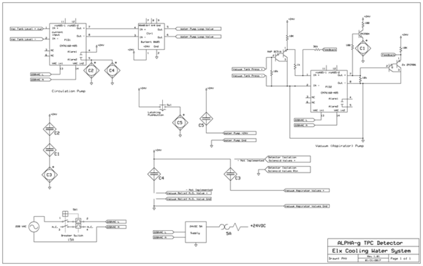
Control Electronics diagram:
Relay Control ladder logic:
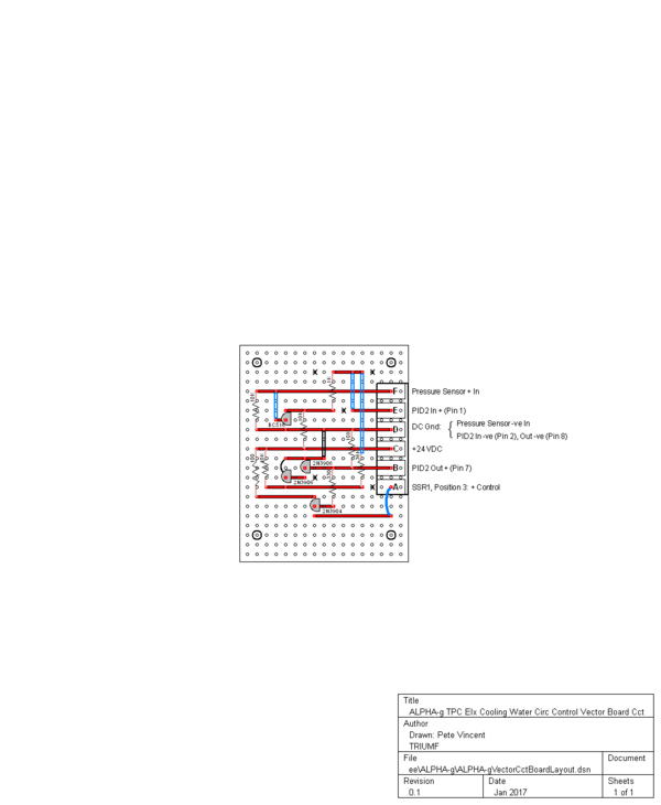
Vector Board circuit layout:
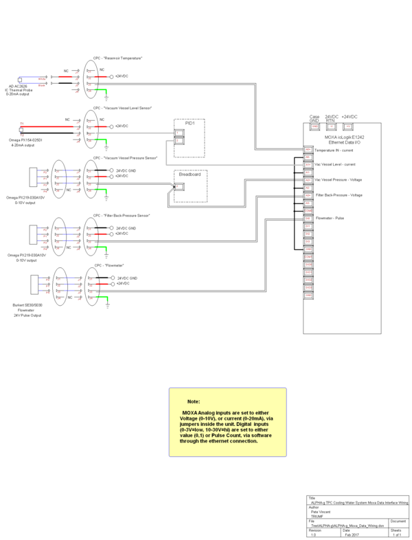
Moxa ioLogik ethernet interface wiring:
Reference
<ref>FrontPanel</ref>
