MVM-IT: Difference between revisions
| Line 804: | Line 804: | ||
</pre> | </pre> | ||
* armdaq10 | * armdaq10 control board "rev 4", notice no error all drivers (good) | ||
<pre> | <pre> | ||
outputs 0 | outputs 0 | ||
| Line 824: | Line 824: | ||
BPwr 2.00 0 | BPwr 2.00 0 | ||
outputs 1 | outputs 1 | ||
</pre> | |||
* armdaq09 control board "rev 4", notice no error all drivers (good) | |||
<pre> | |||
outputs 1 | |||
sensors | |||
PI1 -87.36 0 | |||
PI2 -1.45 0 | |||
PI3 0.68 0 | |||
SF1 133.28 0 | |||
Vsys 11.72 0 | |||
Vrpi 4.95 0 | |||
Vsup 3.32 0 | |||
Vref 2.50 0 | |||
FIO 17.55 0 | |||
Vref2 2.50 0 | |||
Batt 94.30 0 | |||
PI5 4814.60 0 | |||
Vpwr 10.48 0 | |||
Vcnt 4.54 0 | |||
BPwr 2.00 0 | |||
outputs 0 | |||
sensors | |||
</pre> | </pre> | ||
Revision as of 19:04, 10 June 2020
Links
- MVM-IT MVM with Italian control board
- MVM-TR MVM with TRIUMF control board
- ESP32 - ESP32 information: adafruit HUZZA32, ESP-WROOM32 modules, arduino and IDF cross-compilers
- RPI3 - RPi information (SD cards, boot modes, etc)
- Project main page:
- http://mvm.care/
- letter from the Founder and Spokesperson http://mvm.care/wp-content/uploads/2020/04/Lettera-Aperta-Apr-12-2020-EN.pdf
- Main repositories:
- https://github.com/NuclearInstruments/MVMFirmwareCpp - "cpp" firmware repository, including supervisor firmware
- https://github.com/dd1dd1/MVMFirmwareCpp - Konstantin's fork of "cpp" firmware.
- https://github.com/fmselab/mvm-firmware - MVMFirmwareCpp unit tests
- https://github.com/MechanicalVentilatorMilano/gui - GUI repository
- https://github.com/MechanicalVentilatorMilano/firmware-docker-build (private to MVM members) - ???
- https://github.com/MechanicalVentilatorMilano/firmware-libraries (private to MVM members) - new firmware repository
- https://github.com/dd1dd1/MVMFirmwareCpp/issues - firmware code review
- Additional repositories:
- https://github.com/MechanicalVentilatorMilano/mvm-control - mvm-control script to read MVM data (Bryerton)
- https://github.com/MechanicalVentilatorMilano/ControlBoard - hw_rev3 control board ([PDF file is here]
- https://github.com/NuclearInstruments/MVMFirmware - Arduino firmware git repository
- https://github.com/ManuelBeschi/MVMFirmware - Beschi pressure controller development, branch unibs
- https://gitlab.triumf.ca/mvmdev - TRIUMF gitlab repository
- https://gitlab.triumf.ca/mvmdev/gui - TRIUMF copy of mvm_gui (use branch ko_test)
- https://gitlab.triumf.ca/mvmdev/MVMFirmware - TRIUMF copy of mvm firmware (use branch ko_test)
- https://gitlab.triumf.ca/mvmdev/MVMFirmwareCpp - TRIUMF copy of MVMFirmwareCpp (use "ko" branches)
- https://gitlab.triumf.ca/mvmdev/controlboard/-/blob/master/board.pdf - board schematics from ControlBoard git repo
- https://gitlab.triumf.ca/mvmdev/GUIAutoBuild - RPi SD card image generator
Software Quality Assurance
Guiding documents:
- US FDA "emergency use authorization" - https://www.fda.gov/media/136423/download
Organized by Masa and Dave T.:
- main repository https://drive.google.com/drive/folders/19yd3cBtps8ZVCz-VJ8rMLKcV_b80WLdS
- task list (SQA Task List) https://docs.google.com/spreadsheets/d/19ZYdqxHZD_Z2tz578GtEhNLRfs_BdxoojMHiWyw6Nu4
- Software Requirement Specification Communication Protocol https://drive.google.com/file/d/1BfzPRSCjlMvuD0lyCnf98FgVY3Y6Tq7-/view
- SOFTWARE DESIGN DESCRIPTION OF THE INTERFACES https://drive.google.com/file/d/1X-zctXJN14Dob1ziR_mtMZAaQj3FLcSj/view
- Software Work Practice Coding Guideline https://docs.google.com/document/d/1SBw6FDcrIlc-SOpfWioNPTEWER3rW04eRpZBzZWJozA/edit
- Software Procedure Software Development Environment https://docs.google.com/document/d/18_WfIly3p-0-zvbXg3-mGAi8ha3BSTgwKL14qngbi6w/edit
- git repository and wiki: https://github.com/MechanicalVentilatorMilano/mvm-sqa/wiki
Additional repositories:
- SNOLAB sharepoint: https://snolab.sharepoint.com/sites/mvmcanada
MVMFirmwareCpp Code Review:
- scope: https://github.com/MechanicalVentilatorMilano/mvm-sqa/wiki/FirmwareCodeReview-Scope
- git issues: https://github.com/dd1dd1/MVMFirmwareCpp/issues
- doxygen V5: https://ladd00.triumf.ca/~olchansk/MVMFirmareCpp_V5_html/_m_v_m_firmware_core_8ino.html
- doxygen v0.1: https://ladd00.triumf.ca/~olchansk/MVMFirmareCpp_v0.1_html/_m_v_m_firmware_core_8ino.html
Documents under development:
- MVM manual: https://snolab.sharepoint.com/:b:/r/sites/mvmcanada/Shared%20Documents/Manufacturing/MVM%20Manuals/MVM_User_Manual%20(16).pdf?csf=1&web=1&e=kbLEQA
- TRIUMF Requirements for Software Development for Canada-MVM: https://triumfoffice365.sharepoint.com/:w:/r/sites/TRIUMFCOVIDVentilatorTeam/_layouts/15/guestaccess.aspx?e=4%3AwGXYeU&at=9&share=EWREZhBQ7sFAnOGswG1h43QBPvZqoTw_kPjHvAatRpKoJw
- CNL software requirements spec: https://drive.google.com/drive/folders/1E0ut8qkXw89QDiak_fINJ8YZVg-X9yJS
- unsigned MVM Top Level Requirements Specification: https://docs.google.com/document/d/1t9Q1N9lXn3beTZ9OJB4WQUkmIpByikOgQ0jR2diW5O8/edit
MVM Hardware tests:
MVM box
- File:Mvm-gas-wiring.pptx.pdf - MVM internals
- File:Mvm-ventillator23b.pdf - gas piping diagram


hw_rev3
Control board
Per board.pdf dated "4/13/20"
- external power supply:
- VLOGIC 24 VDC (up to 40VDC, LM2596, http://www.ti.com/lit/ds/symlink/lm2596.pdf)
- VPOWER ?? VDC (up to 40VDC, LT8609, https://www.analog.com/media/en/technical-documentation/data-sheets/LT8609-8609A-8609B.pdf)
- Adafruit HUZZA32 module (ESP-WROOM32 ESP32 microcontroller ESP32)
- 6 pressure sensors (5525DSO-DB001DS)
- 2 GPIO pins (J5, CH3, CH4, pull up to 3.3V)
- 2 push button inputs (J6, J7 BTN_1, BTN_2, pull up to 3.3V)
- 2 LED drivers (J8, J9 LED, BUZ, 5V)
- 2 "modulation control" (J10, J11)
- 2 "24V solid state relay" (J12, J13, OMRON_G3VM-61FR1)
- 2 I2C 3.3V (J14, J15)
- 2 I2C 5V (J16, J17)
- 1 ESP32 serial console (J18, 3.3V, RX, TX)
- 1 O2 sensor input (J19, OXY_IN)
- 1 SPI 3.3V (J20A)
System configurations
- "Italian model": [ MVM-IT + ESP32 ] ---- usb-serial ---- [ RPi + GUI ] (remote control) ---- wifi or cat5 or SD/USB flash for data collection
- "2.5 Pi": [ MVM-IT + ESP32 --- usb-serial --- RPi + GUI (local control) ] ---- cat5 ---- [ RPi + GUI ] (remote control)
Notable hardware limitations:
- ESP32: yes wifi, no cat5 ethernet, no usb, no sd flash (sd flash maybe via adafruit LCD "feather")
- RPi: cat5/rj45 ethernet, wifi, HDMI/DP, USB, SD flash slot.
Abbreviations: MVM-IT - Italian PCB, ESP32 - adafruit HUZZA32/WROOM32/ESP32 icrocontroller, RPi - RaspberryPi, GUI - medium size LCD running the MVM python GUI
ESP32 connections
!!! ALL GPIO PINS are 3.3V, NOT 5V safe !!!
ESP32 - link to the ESP32 page
- ESP32 power: per https://learn.adafruit.com/adafruit-huzzah32-esp32-feather/power-management, last "not recommended" option: "Connect an external 5V power supply to the USB and GND pins"
ESP32 pin and name - WROOM32 - HUZZA32 - header - schematic name - function

"JP1 16 pin"

42 - GPIO21 - IO21 - 21      - JP1-1  - CS - (output) SPI nCS - mux GPIO21 or VSPIHD
41 - U0TXD  - TXD0 - TX/17   - JP1-2  - TX  - ESP32 console - mux GPIO1 or U0TXD
40 - U0RXD  - RXD0 - RX/16   - JP1-3  - RX  - ESP32 console - mux GPIO3 or U0RXD
38 - GPIO19 - IO19 - MISO/19 - JP1-4  - MISO  - (input) SPI MISO - mux GPIO19 or U0CTS or VSPIQ
35 - GPIO18 - IO18 - MOSI/18 - JP1-5  - MOSI  - (output) SPI MOSI - mux GPIO18 or VSPICLK
34 - GPIO5  - IO5  - SCK/5   - JP1-6  - SCK  - (output) SPI CLK - mux GPIO5 or VSPICS0
24 - GPIO4  - IO4/A2_0 - ADC2/A5/4 - JP1-7  - N/C - mux GPIO4 or RTC_GPIO10
 5 - SENSOR_VP C16/270pF - IO36/SEN_VP/A1_0 - ADC1/A4/36 - JP1-8  - OXY_IN  - (input only)
 8 - SENSOR_VN C17/270pF - IO39/SEN_VN/A1_3 - ADC1/A3/39 - JP1-9  - BTN_2 - mux GPIO39 or RTC_GPIO3 (input only)
10 - VDET_1 - I34/A1_6       - ADC1/A2/34      - JP1-10 - BTN_1 - mux GPIO34 or RTC_GPIO4 (input only)
14 - GPIO25 - IO25/DAC1/A2_8 - ADC2/A1/DAC1/25 - JP1-11 - DAC1 - mux GPIO25 or RTC_GPIO6 or DAC1
15 - GPIO26 - IO26/DAC2/A2_9 - ADC2/A0/DAC2/26 - JP1-12 - DAC2 - mux GPIO26 or RTC_GPIO7 or DAC2
none - none - GND     - JP1-13 - AGND - GND
none - none - NC      - JP1-14 - N/C
none - none - "3V"    - JP1-15 - "3V"
none - none -  RST    - JP1-16 - "RST"

"JP2 12 pin"

none - none - BAT    - JP3-1  - N/C
none - none - EN     - JP3-2  - N/C
none - none - USB    - JP3-3  - "USB" - 5V USB input power
20 - MTCK   - IO13/A2_4 - "red LED" ADC2/13/A12 - JP3-4  - LED - (output) mux GPIO13 or RTC_GPIO14
18 - MTDI   - IO12/A2_5 - "internal pulldown, output only" ADC2/12/A11 - JP3-5  - BUZ - (output) mux GPIO12 or RTC_GPIO15 - "boot fail if pulled high"
16 - GPIO27 - IO27/A2_7      - ADC2/27/A10 - JP3-6  - CH4 - (output) mux GPIO27 or RTC_GPIO17
13 - 32K_XN - IO33/A1_5/X32N - ADC1/33/A9  - JP3-7  - CH3 - (output) mux GPIO33 or RTC_GPIO8
21 - MTDO   - IO15/A2_3      - ADC2/15/A8  - JP3-8  - CH2 - (output) mux GPIO15 or RTC_GPIO13
12 - 32K_XP - IO32/A1_4/X32P - ADC1/32/A7  - JP3-9  - CH1 - (output) mux GPIO32 or RTC_GPIO9
17 - MTMS   - IO14/A2_6      - ADC2/14/A6  - JP3-10 - "BATTERY" - pull up to 3.3V, mux GPIO14 or RTC_GPIO16 (note: ADC2 cannot be used if Wifi active)
39 - GPIO22 - IO22 - SCL/22 - JP3-11 - "SCL" - (I2C, pull up to 3.3V) - mux GPIO22 or U0RTS
36 - GPIO23 - IO23 - SDA/23 - JP3-12 - "SDA" - (I2C, pull up to 3.3V) - mux GPIO23

not on header, internally connected on HUZZA32:

11 - VDET_2 - I35/A1_7 - ADC1/35/A13 - N/C - VBAT voltmeter (through divider) - mux GPIO35 or ADC1_CH7 or RTC_GPIO5 (input only)

not clear what function:

23 - GPIO0   - IO0/A2_1 - GPIO0 - serial RTS - mux GPIO0 or RTC_GPIO11
22 - GPIO2   - IO2/A2_2 - GPIO2 - serial DTR (looks like mistake on schematic) - mux GPIO2 or RTC_GPIO12
25 - GPIO16  - IO16 - IO16 - not connected? - mux GPIO16 or U2RXD
27 - GPIO17  - IO17 - IO17 - not connected? - mux GPIO17 or U2TXD
 9 - CHIP_PU - EN - RESET - push button - no mux

WROOM32 flash memory connection ("U3"):

28 - SD_DATA_2 - SD2 - n/c - mux SD_DATA2 or GPIO9
29 - SD_DATA_3 - SD3 - n/c - mux SD_DATA3 or GPIO10
30 - SD_CMD - CMD - n/c - mux SD_CMD or GPIO11
31 - SD_CLK - CLK - n/c - mux SD_CLK or GPIO6
32 - SD_DATA_0 - SD0 - n/c - mux SD_DATA0 or GPIO7
33 - SD_DATA_1 - SD1 - n/c - mux SD_DATA1 or GPIO8

Not connected to ESP32:

CPU AUX - (maybe output) direct connection to AUX screw terminal

Note:
- I2C controller can use any/all GPIO pins
- SPI controller can use any/all GPIO pins
I2C bus configuration
- ESP32 drives SCL_UC/SDA_UC, connected are:
- U9 "nano dac", part unknown, maybe not installed
- I2C mux TCA9548APWR (A0,A1,A2 tied to GND), output ports:
- 0 - 3V I2C J14
- 1 - 3V I2C J15
- 2 - 5V I2C J16
- 3 - 5V I2C J17
- 4 - PS1 (CSB tied to 3.3V), PS2 (CSB tied to GND)
- 5 - PS3, PS4 (same CSB)
- 6 - PS5, PS6 (same CSB) (maybe absent)
- 7 - N/C
I2C bus addresses
TO BE UPDATED
* 0x70 - I2C switch - U1 - TI TCA9548APWR [[https://edev-group.triumf.ca/hw/ventilator-controller/rev0/-/blob/master/Altium/Datasheets/tca9548a%20-%20I2C%20switch%208-channel.pdf Datasheet]]
* 0x76 - pressure sensor - i2c switch port 7 mask 0x80 - "TE Connectivity Measurement Specialties" 5525DSO-DB001DS [[https://edev-group.triumf.ca/hw/ventilator-controller/rev0/-/blob/master/Altium/Datasheets/MS5525DSO_D20-1%20pressure%20sensor.pdf Datasheet]]
* 0x80 - flow meter - i2c switch port 0 mask 0x01 - SFM3000 - https://gitlab.triumf.ca/mvmdev/mvmcontroller/-/blob/dev-esp32/docs/datasheets/Sensirion-Mass-Flow-Meters-SFM3000-I2C-Functional-Description.pdf https://gitlab.triumf.ca/mvmdev/mvmcontroller/-/blob/dev-esp32/docs/datasheets/Sensirion_Mass_Flow_Meters_SFM3000_Datasheet.pdf https://gitlab.triumf.ca/mvmdev/mvmcontroller/-/blob/dev-esp32/docs/datasheets/SFM3xxx_Extended_I2C_Command_Set.pdf

To probe the pressure sensor:
<pre>
$ i2cset -y 1 0x70 0 0x80
$ i2cget -y 1 0x70
0x80
$ i2cdetect -y 1 ### detects: 0x70 (switch) and 0x76 (pressure sensor)
     0  1  2  3  4  5  6  7  8  9  a  b  c  d  e  f
00:          -- -- -- -- -- -- -- -- -- -- -- -- --
10: -- -- -- -- -- -- -- -- -- -- -- -- -- -- -- --
20: -- -- -- -- -- -- -- -- -- -- -- -- -- -- -- --
30: -- -- -- -- -- -- -- -- -- -- -- -- -- -- -- --
40: -- -- -- -- -- -- -- -- -- -- -- -- -- -- -- --
50: -- -- -- -- -- -- -- -- -- -- -- -- -- -- -- --
60: -- -- -- -- -- -- -- -- -- -- -- -- -- -- -- --
70: 70 -- -- -- -- -- 76 --
hw_rev4
Info from A.Abba
-------- Forwarded Message --------
Subject:        R: desktop environment and coding guidance
Date:   Sun, 3 May 2020 20:25:08 +0000
From:   Andrea Abba <abba@nuclearinstruments.eu>
To:     Pierre-A. Amaudruz <amaudruz@triumf.ca>, Alessandro Razeto
<alessandro.razeto@lngs.infn.it>
CC:     Cristiano Galbiati <galbiati@princeton.edu>, Marc F Paterno
<paterno@fnal.gov>


Dear Pierre,
answering to your question is not streight forward as should be.

In the project the following microcontroller are involved:

  * CONTROLLER:   ESP32-WROOM-32. This is a IOT chip designed to be a
    flexible wireless SoC (System on Chip). It is a dual core ARM 32 bit
    chip
  * SUPERVISOR: ATMEGA328P-MU. It is a 8 bit microcontroller extremely
    used in several application.


Both microcontroller, as per initial specification, uses Arduino
enviromental. It does not simply mean that we use arduino ide to program
but it means that there is a layer between hardware and firmware that
abstract all microcontroller main functionalities.

Unfortunately is not very easy to track what happens in the arduino
layer. The tools have auto update functionalities but i can right now
make a snapshot of the situation on my computer

ESP32

Following items are involved:

  * Arduino IDE:  v1.8.12
  * Community libraries: SimpliCLI 1.0.8, Wire 1.0.1
  * ESP32 toolchain: xtensa-esp32-elf-gcc  1.22.0-80-g6c4433a-5.2.0

The module used is the Adafruit ESP32 Feather but on the board there is
also the possibility to direct soder the ESP32-WROOM-32 in the exact
configuration of the Feather board (so it's identical)

ATMEGA328P-MU
It is configured as Arduino PRO @ 3.3V 8MHz

  * Arduino IDE:  v1.8.12
  * Community libraries: SoftWire (V3 the correct version is included in
    the repository), Wire 1.0
  * Toolchain: AVR GCC/G++ 7.3.0


Don't esitate to contact me if you need more information
------------------------------------------------------------------------
Control board
TBW, waiting for board schematics
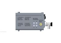
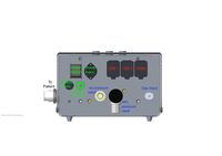
Diagram from unknown source: https://ladd00.triumf.ca/~olchansk/block-diag-01.pdf
System architecture
valves, sensors ---i2c--- ESP32 ---esp32-u0-serial---serial-usb-bridge-|---usb-cable---|---RPi4B---|---LCD screen

sensors,etc ---i2c--- "supervisor microcontroller" --- connected to TBW, waiting for board schematics
ESP32 connections
!!! ALL GPIO PINS are 3.3V, NOT 5V safe !!!
ESP32 - link to the ESP32 page
TBW, waiting for board schematics
I2C bus configuration
- ESP32 drives SCL_UC/SDA_UC, connected are:
TBW, waiting for board schematics
I2C bus addresses
TBW, waiting for board schematics
Supervisor Interface
uint16_t HW_V4::ReadSupervisor(uint8_t i_address) ...

$ grep ReadSupervisor *.cpp
fw_board_ni_v4.cpp:		pIN = ((float)ReadSupervisor(0x50));
fw_board_ni_v4.cpp:		currentBatteryCharge = (float)ReadSupervisor(0x51);
fw_board_ni_v4.cpp:		pWall = ReadSupervisor(0x52) >0 ? false : true ;
fw_board_ni_v4.cpp:		BoardTemperature = ((float)ReadSupervisor(0x56)/10.0);
fw_board_ni_v4.cpp:		HW_AlarmsFlags = (uint16_t)ReadSupervisor(0x57);
WriteSupervisor(0x00, 1); // reset supervisor watchdog
WriteSupervisor(0x01, 1); // enable supervisor watchdogh
Pressure sensor
Calibration constants (chip on KO's board):
read by i2cget (addr 0xa0 through 0xae)
pi@raspberrypi:~ $ i2cget -y 1 0x76 0xa0 w
0x0100
read by sensors.exe (branch dev-linux)
pressure sensor PROM 0x00: 0x0001
pressure sensor PROM 0x01: 0x392b
pressure sensor PROM 0x02: 0x1e52
pressure sensor PROM 0x03: 0x0e25
pressure sensor PROM 0x04: 0x071a
pressure sensor PROM 0x05: 0x943d
pressure sensor PROM 0x06: 0x1f6b
pressure sensor PROM 0x07: 0x000c
mvm_hal_init: PS1 CRC4 OK!
- read ADC, no conversion
root@raspberrypi:~/i2c-tools-4.1/tools# ./i2cget3 -y 1 0x76 0
write returned 1
read returned 4, value 0x3f000000
- read ADC, pressure
i2cset -y 1 0x76 0x48
root@raspberrypi:~/i2c-tools-4.1/tools# ./i2cget3 -y 1 0x76 0
write returned 1
read returned 4, value 0x3f900a44
- read ADC, temperature
i2cset -y 1 0x76 0x58
root@raspberrypi:~/i2c-tools-4.1/tools# ./i2cget3 -y 1 0x76 0
write returned 1
read returned 4, value 0x3f9c424d
Flow sensor
TBW
Proportional Valve ArduinoCorePP_PWM_hw_v3 firmware
- From Bryerton:
The Italian's use the PWM on DAC1 / A0 / IO25 pin. The API is the ledc API used to control an LED via PWM
- see ArduinoCorePP_PWM_hw_v3.ino
- function setup() attach pin "DAC1" to ledc
ledcSetup(0, 10000, 12); // KO: chan 0, freq in kHz, how many bits of PWM 12 bits = range 0..4095
ledcAttachPin(DAC1, 0); // KO: IO25/A0/DAC1
ledcWrite(0, 0);
- function PressureControlLoop_PRESSIN() see ledcWrite()
if (Pset == 0) {
  ledcWrite(0, 0);
} else {
  pid_outb = ...; // KO: looks like a digital PID controller
  if (pid_outb<0) pid_outb=0; // KO: low limit
  pid_outb = pid_outb + 500; // KO: what is this?!?
  if (pid_outb>4090) pid_outb=4090; // KO: high limit
  ledcWrite(0, pid_outb); // KO: value 500..4090
}
- also see valve_control() commented absent code for PWM.
MVM-GUI
Code review
- pdoc diagrams - https://home.fnal.gov/~mwang/mvm/sqa/gui/html/index.html
Install
- as root:
- apt-get update
- apt-get install python3-pyqt5 python3-numpy python3-pyqtgraph python3-serial
- ### does not work, installs wrong pip: apt-get install python3-pip
- curl https://bootstrap.pypa.io/get-pip.py -o get-pip.py
- python3 get-pip.py --force-reinstall
- ### does not work, installs too-old version of yaml 3.13: apt-get install python3-yaml
- pip3 install PyYAML ### version 5.3.1
- pip3 install crc8 ### version 0.1.0
- ssh pi@rpi
- #git clone https://github.com/MechanicalVentilatorMilano/gui.git
- #git clone https://gitlab.triumf.ca/mvmdev/gui.git
- #git checkout ko_test
- git clone git@github.com:MechanicalVentilatorMilano/gui.git ### only members of github "MVM project" can access!
Run with python simulator
- cd gui
- ./mvm_gui.py fakeESP32
Run with ESP32 simulator
- load the ardiuno sketch mock/mock.ino into ESP32 (see instructions below)
- ./mvm_gui.py ### default connection is /dev/ttyUSB0 at 115200 bps, change it in default_settings.yaml
MVMFirmware monolithic hw_rev3, hw_rev4
Prepare
- install arduino: https://daq.triumf.ca/DaqWiki/index.php/ESP32#Arduino_IDE
Build and Flash
- ssh pi@...
- ### use TRIUMF gitlab branch ko_test instead ### git clone https://github.com/NuclearInstruments/MVMFirmware.git
- git clone https://gitlab.triumf.ca/mvmdev/MVMFirmware.git
- git checkout ko_test
- cd arduino; ./ardiuno
- open .../MVMFirmware/ArduinoCorePP_PWM_hw_v3/ArduinoCorePP_PWM_hw_v3.ino
- install library SimpleCLI (1.0.9), aREST (2.8.0)
- build sketch (there is warnings about TwoWire::requestFrom())
- load sketch
Connect and Use manually
- use Ardiuno tools -> serial console, set: serial 115200
- or use minicom, set /dev/ttyUSB0, 115200 bps, no flow control
- output on a base esp32 (no baseboard, no hardware, no sensors, etc)
ets Jun  8 2016 00:22:57

rst:0x1 (POWERON_RESET),boot:0x13 (SPI_FAST_FLASH_BOOT)
configsip: 0, SPIWP:0xee
clk_drv:0x00,q_drv:0x00,d_drv:0x00,cs0_drv:0x00,hd_drv:0x00,wp_drv:0x00
mode:DIO, clock div:1
load:0x3fff0018,len:4
load:0x3fff001c,len:1044
load:0x40078000,len:8896
load:0x40080400,len:5816
entry 0x400806ac
SCAN I2C BUS: 0
Scanning... I2C
No I2C devices found

SCAN I2C BUS: 1
Scanning... I2C
No I2C devices found

SCAN I2C BUS: 2
Scanning... I2C
No I2C devices found

SCAN I2C BUS: 3
Scanning... I2C
No I2C devices found

SCAN I2C BUS: 4
Scanning... I2C
No I2C devices found

SCAN I2C BUS: 5
Scanning... I2C
No I2C devices found

SCAN I2C BUS: 6
Scanning... I2C
No I2C devices found

SCAN I2C BUS: 7
Scanning... I2C
No I2C devices found

SENSOR:           0
SENS_T1:          65535
OFF_T1:           65535
TCS:              65535
TCO:              65535
TREF:             65535
TEMPSENS:         65535
OFFSET:            0.00
SENSOR:           1
SENS_T1:          65535
OFF_T1:           65535
TCS:              65535
TCO:              65535
TREF:             65535
TEMPSENS:         65535
OFFSET:            0.00
SENSOR:           2
SENS_T1:          65535
OFF_T1:           65535
TCS:              65535
TCO:              65535
TREF:             65535
TEMPSENS:         65535
OFFSET:            0.00
SENSOR:           3
SENS_T1:          65535
OFF_T1:           65535
TCS:              65535
TCO:              65535
TREF:             65535
TEMPSENS:         65535
OFFSET:            0.00
SFM driver version 0.1.0
SFM sensor probing failed
...
Measure Flow Sensor initialized!
- send: "get all", reply: "valore=0.00,0.00,0,0,0,0,0,0,1"
Connect and read data using mvm-control
Follow the README file at: https://github.com/MechanicalVentilatorMilano/mvm-control
MVMFirmwareCpp
Prepare
- install arduino: https://daq.triumf.ca/DaqWiki/index.php/ESP32#Arduino_IDE
- install arduino library SimpleCLI (1.0.9)
Build and Flash
- ssh pi@...
- ### git clone git@github.com:NuclearInstruments/MVMFirmwareCpp.git
- git clone git@github.com:dd1dd1/MVMFirmwareCpp.git ### Konstantin's github via ssh
- git clone https://github.com/dd1dd1/MVMFirmwareCpp.git ### Konstantin's github via https
- cd MVMFirmwareCpp
- git checkout ko1 ### get the "V5" firmware
- git checkout v0.1_ko2 ### git the "v0.1" firmware
- ~/arduino-1.8.12/arduino MVMFirmwareCore.ino
- install library SimpleCLI (1.0.9)
- build sketch
- firmware tag "V5" and "v0.1" will fail with error about missing arduino.h. Please use tag "V5_ko1a" or "v0.1_ko2a" instead from Konstantin's github.
- upload sketch into esp32
Connect and Use manually
- use Ardiuno tools -> serial console, set: serial 115200
- or use minicom, set /dev/ttyUSB0, 115200 bps, no flow control
- output on a base esp32 (no baseboard, no hardware, no sensors, etc)
...
- send: "get all", reply: "valore=..."
Connect and read data using mvm-control
Follow the README file at: https://github.com/MechanicalVentilatorMilano/mvm-control
- git clone https://github.com/MechanicalVentilatorMilano/mvm-control.git
- cd mvm-control
- python mvm_control.py -p /dev/ttyUSB0 log
{"time":1.717,"p_patient":0.00,"f_total":0.00,"o2":100.00,"bpm":0.00,"v_total":0.00,"peep":0.00,"temp":0.00,"bat_pwr":1,"bat_charge":100.00,"p_peak":0.00,"v_total_insp":0.00,"v_total_exhl":0.00,"f_peak":0.00},
...
Connect with mvm_gui
See below for instructions to install mvm_gui
- cd gui/gui
- ./mvm_gui.py
MVMFirmware "integration"
- note1: only members of github "MVM project" can see and access the repositories
- note2: from here: https://github.com/MechanicalVentilatorMilano/integration
- install arduino-cli (to $HOME/bin), see https://arduino.github.io/arduino-cli/installation/
curl -fsSL https://raw.githubusercontent.com/arduino/arduino-cli/master/install.sh | sh
- install arduino libraries
arduino-cli lib install CRC32 ### version 2.0.0
arduino-cli lib install CircularBuffer ### version 1.3.3
arduino-cli lib install AsyncDelay ### version 1.1.0
- clone and build the firmware
mkdir -p mvm
cd mvm
git clone git@github.com:MechanicalVentilatorMilano/integration.git
cd integration
git submodule sync
git submodule init
git submodule update
make
- load arduino sketch into esp32
arduino-cli upload ./framework --fqbn "esp32:esp32:featheresp32:FlashFreq=80,UploadSpeed=115200,DebugLevel=none,PartitionScheme=default" -p /dev/ttyUSB0
- watch it run, "tail -100f /dev/ttyUSB0" or minicom. no flow control, 115200 bps. (firmware prints nothing after the "load..." and "entry..." messages.
eeprom utility
- build and run the eeprom utility to setup a new control board:
pi@raspberrypi:~/integration $ make eeprom
arduino-cli compile --warnings all --build-properties "compiler.warning_flags.all=-Wall -Wextra" --fqbn "esp32:esp32:featheresp32:FlashFreq=80,UploadSpeed=115200,DebugLevel=none,PartitionScheme=default" --build-properties "build.defines=-DMVM" --libraries /home/pi/integration/libraries libraries/hal/examples/eeprom
Sketch uses 227157 bytes (17%) of program storage space. Maximum is 1310720 bytes.
Global variables use 16668 bytes (5%) of dynamic memory, leaving 311012 bytes for local variables. Maximum is 327680 bytes.
pi@raspberrypi:~/integration $ make eeprom.upload
arduino-cli upload libraries/hal/examples/eeprom --fqbn "esp32:esp32:featheresp32:FlashFreq=80,UploadSpeed=115200,DebugLevel=none,PartitionScheme=default" -p /dev/ttyUSB0
- bare esp32 ... in minicom:
ets Jun  8 2016 00:22:57

rst:0x1 (POWERON_RESET),boot:0x13 (SPI_FAST_FLASH_BOOT)
configsip: 0, SPIWP:0xee
clk_drv:0x00,q_drv:0x00,d_drv:0x00,cs0_drv:0x00,hd_drv:0x00,wp_drv:0x00
mode:DIO, clock div:1
load:0x3fff0018,len:4
load:0x3fff001c,len:1044
load:0x40078000,len:8896
load:0x40080400,len:5816
entry 0x400806ac
A 0 8
A 1 8
A 2 8
A 3 8
A 4 8
A 5 8
A 6 8
S 0 8
S 1 8
S 2 8
S 3 8
S 4 8
S 5 8
S 6 8
S 7 8
S 8 8
S 9 8
Done programming
H C 199 K 49 A 7 S 10 SDA 16 SCL 27
ACT 0 crc 0 type F subtype 0 inv 0 pin 0 dfl 0 id 0 status 8
ACT 1 crc 0 type F subtype 0 inv 0 pin 0 dfl 0 id 0 status 8
ACT 2 crc 0 type F subtype 0 inv 0 pin 0 dfl 0 id 0 status 8
ACT 3 crc 0 type F subtype 0 inv 0 pin 0 dfl 0 id 0 status 8
ACT 4 crc 0 type F subtype 0 inv 0 pin 0 dfl 0 id 0 status 8
ACT 5 crc 0 type F subtype 0 inv 0 pin 0 dfl 0 id 0 status 8
ACT 6 crc 0 type F subtype 0 inv 0 pin 0 dfl 0 id 0 status 8
ACT 7 crc 0 type F subtype 0 inv 0 pin 0 dfl 0 id 0 status 8
SNS 0 crc 0 type F subtype 0 id 0 bus 0 mux 0 addr 0 status 8
SNS 1 crc 0 type F subtype 0 id 0 bus 0 mux 0 addr 0 status 8
SNS 2 crc 0 type F subtype 0 id 0 bus 0 mux 0 addr 0 status 8
SNS 3 crc 0 type F subtype 0 id 0 bus 0 mux 0 addr 0 status 8
SNS 4 crc 0 type F subtype 0 id 0 bus 0 mux 0 addr 0 status 8
SNS 5 crc 0 type F subtype 0 id 0 bus 0 mux 0 addr 0 status 8
SNS 6 crc 0 type F subtype 0 id 0 bus 0 mux 0 addr 0 status 8
SNS 7 crc 0 type F subtype 0 id 0 bus 0 mux 0 addr 0 status 8
SNS 8 crc 0 type F subtype 0 id 0 bus 0 mux 0 addr 0 status 8
SNS 9 crc 0 type F subtype 0 id 0 bus 0 mux 0 addr 0 status 8
SNS 10 crc 0 type F subtype 0 id 0 bus 0 mux 0 addr 0 status 8
- control board "rev 4"
Done programming
H C 199 K 49 A 7 S 10 SDA 16 SCL 27
ACT 0 crc 43 type 0 subtype 1 inv 1 pin 19 dfl 0 id 0 status 0
ACT 1 crc 45 type 0 subtype 0 inv 1 pin 20 dfl 0 id 20 status 0
ACT 2 crc C4 type 0 subtype 0 inv 0 pin 4 dfl 0 id 30 status 0
ACT 3 crc 2E type 0 subtype 0 inv 0 pin D dfl 0 id 40 status 0
ACT 4 crc F5 type 0 subtype 0 inv 0 pin 11 dfl 0 id 50 status 0
ACT 5 crc DB type 0 subtype 0 inv 0 pin C dfl 0 id 60 status 0
ACT 6 crc 41 type 0 subtype 0 inv 0 pin 15 dfl 0 id 70 status 0
ACT 7 crc 41 type F subtype 0 inv 0 pin 15 dfl 0 id 70 status 0
SNS 0 crc A1 type 0 subtype 0 id 0 bus 0 mux 2 addr 77 status 0
SNS 1 crc DE type 0 subtype 0 id 10 bus 0 mux 1 addr 77 status 0
SNS 2 crc 4B type 1 subtype 2 id 20 bus 1 mux FFFFFFFF addr 28 status 0
SNS 3 crc 7F type 4 subtype 0 id 40 bus 0 mux 5 addr 0 status 0
SNS 4 crc 33 type 6 subtype 0 id 60 bus 0 mux 3 addr 0 status 0
SNS 5 crc E4 type 2 subtype 0 id 70 bus 0 mux 4 addr 49 status 0
SNS 6 crc 43 type 2 subtype 0 id FFFFFF80 bus 0 mux 4 addr 48 status 0
SNS 7 crc 6A type 5 subtype 1 id FFFFFFA0 bus FFFFFFFF mux 0 addr 27 status 0
SNS 8 crc B9 type 5 subtype 1 id FFFFFFB0 bus FFFFFFFF mux 0 addr 22 status 0
SNS 9 crc BC type 5 subtype 0 id FFFFFFC0 bus FFFFFFFF mux 0 addr F status 0
SNS 10 crc BC type F subtype 0 id FFFFFFC0 bus FFFFFFFF mux 0 addr F status 0
HAL utility
The HAL utility prints values of all sensors & etc:
- build:
pi@raspberrypi:~/integration $ make HAL
arduino-cli compile --warnings all --build-properties "compiler.warning_flags.all=-Wall -Wextra" --fqbn "esp32:esp32:featheresp32:FlashFreq=80,UploadSpeed=115200,DebugLevel=none,PartitionScheme=default" --build-properties "build.defines=-DMVM" --libraries /home/pi/integration/libraries libraries/hal/examples/HAL
Sketch uses 238185 bytes (18%) of program storage space. Maximum is 1310720 bytes.
Global variables use 16476 bytes (5%) of dynamic memory, leaving 311204 bytes for local variables. Maximum is 327680 bytes.
pi@raspberrypi:~/integration $ make HAL.upload
arduino-cli upload libraries/hal/examples/HAL --fqbn "esp32:esp32:featheresp32:FlashFreq=80,UploadSpeed=115200,DebugLevel=none,PartitionScheme=default" -p /dev/ttyUSB0
- bare esp32
outputs 0
sensors
PI1 0.00 -100
PI2 0.00 -100
PI3 0.00 -100
SF1 0.00 -100
Vsys 0.00 -100
Vrpi 0.00 -100
Vsup 0.00 -100
Vref 0.00 -100
FIO 0.00 -100
Vref2 0.00 -100
Batt 0.00 -100
PI5 0.00 -100
Vpwr 0.00 -100
Vcnt 0.00 -100
BPwr 0.00 -100
outputs 1
- control board "rev 4", notice failure of PI2, PI3, SF1
outputs 0
sensors
PI1 -87.19 0
PI2 -1.47 -5
PI3 -1.18 -1
SF1 -239.94 2
Vsys 11.74 0
Vrpi 4.97 0
Vsup 3.32 0
Vref 2.50 0
FIO 16.81 0
Vref2 2.50 0
Batt 94.80 0
PI5 1157.88 0
Vpwr 10.35 0
Vcnt 4.51 0
BPwr 2.00 0
outputs 1
- armdaq10 control board "rev 4", notice no error all drivers (good)
outputs 0
sensors
PI1 -121.42 0
PI2 17.28 0
PI3 32.21 0
SF1 0.83 0
Vsys 11.77 0
Vrpi 4.97 0
Vsup 3.32 0
Vref 2.50 0
FIO 4.19 0
Vef2 2.50 0
Batt 94.79 0
PI5 4805.77 0
Vpwr 10.81 0
Vcnt 4.64 0
BPwr 2.00 0
outputs 1
- armdaq09 control board "rev 4", notice no error all drivers (good)
outputs 1
sensors
PI1 -87.36 0
PI2 -1.45 0
PI3 0.68 0
SF1 133.28 0
Vsys 11.72 0
Vrpi 4.95 0
Vsup 3.32 0
Vref 2.50 0
FIO 17.55 0
Vref2 2.50 0
Batt 94.30 0
PI5 4814.60 0
Vpwr 10.48 0
Vcnt 4.54 0
BPwr 2.00 0
outputs 0
sensors
Supervisor
- note1: only members of github "MVM project" can see and access the supervisor repository
- install and build
mkdir -p mvm
cd mvm
git clone git@github.com:MechanicalVentilatorMilano/supervisor.git
cd supervisor/
make AVR_TOOL_PATH=$HOME/arduino-1.8.12/hardware/tools/avr/bin/
# supervisor.elf and supervisor.hex are created
- upload to supervisor flash memory
fake it!
Firmware to GUI interface
Physical link
USB serial, 115200 bps, usb-serial lines RTS and DSR control reset and programming mode of esp32 processor.
The firmware running inside the ESP32 microcontroller communicates with the outside world using the U0TXD/U0RXD serial interface at 115200 bps, 8 bit, no flow control.
The adafruit HUZZAH32 ESP32 board integrates a serial-to-USB bridge chip and a micro-USB connector. The bridge chip implements a USB-serial communication protocal and provides a way to reset the ESP32 and to cause the ESP32 to enter the flash programming mode by operating the RTS and DSR lines.
Computer running the GUI code should connect to the ESP32 running the MVM firmware using a USB cable (micro-USB to USB-A). On Linux (i.e. RPi4 display unit) GUI should be configured to access /dev/ttyUSB0 with serial port settings listed above.
Set commands
| set command | version | type | arguments |
|---|---|---|---|
| "run" | all | int | <1: core_config.run=false, else =true |
| "mode" | all | int | 0: BreathMode=M_BREATH_FORCED, else =M_BREATH_ASSISTED |
| "rate" | all | float | core_config.respiratory_rate |
| "ratio" | all | float | core_config.respiratory_ratio |
| "assist_ptrigger | all | float | core_config.assist_pressure_delta_trigger |
| "assist_flow_min" | all | float | flux_close |
| "ptarget | all | float | target_pressure_auto |
| "pressure_support" | all | float | target_ressure_assist |
| "peep" | hw_rev3, hw_rev4 | float | pressure_forced_exhale_min, REMOVED IN V5 |
| "pid_p" | all | float | .P |
| "pid_i" | all | float | .I |
| "pid_d" | all | float | .D |
| "pid_p2" | all | float | .P2 |
| "pid_i2" | all | float | .I2 |
| "pid_d2" | all | float | .D2 |
| "pause_inhale" | all | int | pause_inhale=arg, pause_timeout=500 |
| "pause_lg" | all | int | !=0, pause_lg=true, else =false |
| "pause_lg_time" | all | float->int | pause_lg_timer = arg*1000.0 |
| "pause_lg_p" | all | float->int | pause_lg_p |
| "pause_inhale" | v0.1 | int | pause_inhale=arg, pause_timeout=500 |
| "pause_exhale" | all | int | pause_exhale=arg, pause_timeout=500 |
| "pid_limit" | all | float | pid.limit |
| "alarm_snooze" | all | int | see alarm snooze function |
| "alarm" | hw_rev3, hw_rev4 | int | arg not used, fires ALARM_GUI_ALARM |
| "alarm" | V5, v0.1 | int | set and clear GUI alarm, see alarm function |
| "alarm_test" | v0.1 | int | arg!=0, SetAlarmTest(true), else ALARM_FLAG=0 (clear all alarms) |
| "watchdog_reset" | all | int | arg not used, see watchdog function |
| "console" | all | int | !0, __CONSOLE_MODE=true, else =false |
| "timestamp" | all | int | !0, _ADDTimeStamp=true, else =false |
| "pcv_trigger_enable" | !hw_rev3, hw_v4, V5, v0.1 | int | !0, pcv_trigger_enable=true, else =false |
| "pcv_trigger" | !hw_rev3, hw_v4, V5, v0.1 | float | pcv_trigger |
| "wdenable" | all | int | !0, __WDENABLE=true, else =false; enables and disabled the watchdog, see watchdog function |
| "backup_enable" | all | int | !0, backup_enable=true, else =false |
| "backup_min_rate" | hw_rev3, hw_rev4 | float | <1, backup_min_rate=1, else =arg, REMOVED IN V5 |
| "backup_min_time" | only V5, v0.1 | float | <1, backup_min_rate=1, else =arg |
| "stats_clear" | hw_rev3, hw_rev4 | none | ResetStatsBegin() |
| "stats_clear" | V5, v0.1 | none | does nothing |
| "flush_pipe" | V5, v0.1 | float | <1, FlushPipes(false,1), else FlushPipes(true,arg) |
| "leak_compensation" | v0.1 | float | leak_compensaton |
| "epc" | v0.1 | float | if <1, enable_pressure_compensaton=false, else =true |
| "apnea_rate" | v0.1 | float | apnea_rate |
| "apnea_ratio | v0.1 | float | apnea_ratio |
| "apnea_ptarget" | v0.1 | float | apnea_ptarget |
| "venturi_coefficient_0..4" | v0.1 | float | MVM->VenturiSetCoefficient(0..4, arg) |
Get commands
Get commands respond with "valore="+data, where data is shown in the following table.
- hw_rev3, hw_rev4: unknown commands produce no response
- V5: unknown commands return "valore=ERROR:Invalid Command Argument"
| get command | version | returns | unit | source |
|---|---|---|---|---|
| "pinput" | hw_v4 | Pinput | ? | |
| "pressure" | all | pressure[0].last-pressure; V5: Ploop | ? | PS_0 |
| "ppressure" | V5, v0.1 | PPatient | ? | PS_1 |
| "flow" | all | gasflux[0].last_flux; V5: FlowIn | ? | FLOW1 |
| "o2" | hw_rev3 | last_O2=21.7 | %pct | hardwired 21.7 |
| "o2" | hw_rev4, V5, v0.1 | last_O2 | ? | i2c adc_channel 0 |
| "bpm" | all | last_bpm | ? | |
| "backup" | all | 0, not implemented | - |  |
| "backup" | v0.1 | backup_apnea | bool |  |
| "tidal" | all | tidal_volume_c.TidalVolume*VOL_COMP; V5: TidalVolume | ? | |
| "peep" | all | last_peep | ? | averaged_PPatient |
| "temperature" | all | temperature; V5, v0.1: GasTemperature | ? | FLOW1 temperature |
| "power_mode" | all | "1" if batteryPowered, else "0" |  bool | ReadSupervisor(0x52) |
| "battery" | all | currentBatteryCharge | ? | ReadSupervisor(0x51) |
| "version" | all | _FIRMWARE_VERSION_ | string | |
| "version" | hw_rev3 | "HW_V3_2020_04_15_00" | string | |
| "version" | hw_rev4 | "HW_V4_2020_04_20_00" | string | |
| "version" | V5 | "NI_MVM-HW_V3_2020_04_17_00" | string | FwVersion.h |
| "version" | v0.1 | "NI_MVMCPP-HW_V4_2020_05_01_00" | string | FwVersion.h |
| "alarm" | all | ALARM_FLAG, see alarm function | uint32_t | |
| "warning" | all | 0; V5: WARNING_FLAG, always 0. not implemented | - | - |
| "run" | all | "1" if core_config.run, else "0" | bool | |
| "mode" | all | "1" if core_config.BreathMode == M_BREATH_ASSISTED, else "0" | bool | |
| "rate" | all | core_config.respiratory_rate | ? | |
| "ratio" | all | core_config.respiratory_ratio | ? | |
| "assist_ptrigger" | all | core_config.assist_pressure_delta_trigger | ? | |
| "assist_flow_min" | all | core_config.flux_close | ? | |
| "ptarget" | all | core_config.target_pressure_auto | ? | |
| "pressure_support" | all | core_config.target_pressure_assist | ? | |
| "backup_enable" | all | 1 if core_config.backup_enable, else 0 | bool | |
| "backup_min_rate" | hw_rev3, V5, v0.1 | core_config.backup_min_rate | ? | |
| "backup_min_time" | hw_rev4 | core_config.backup_min_time | ? | |
| "pause_lg" | all | core_config.pause_lg | ? | |
| "pause_lg_time" | all | core_config.pause_lg_timer/1000.0 | ? | |
| "pause_lg_p" | all | core_config.pause_lg_p | ? | |
| "leak_compensation" | v0.1 | core_config.leak_compensation | ? | |
| "apnea_rate" | v0.1 | apnea_rate | ? | |
| "apnea_ratio" | v0.1 | apnea_ratio | ? | |
| "apnea_ptarget" | v0.1 | apnea_ptarget | ? | |
| "pin" | v0.1 | Pin | float | ReadSupervisor(0x50) |
| "btemp" | v0.1 | BoardTemperature | float | ReadSupervisor(0x56) |
| "salarm" | v0.1 | SupervisorAlarms | uint16_t  | ReadSupervisor(0x57) |
| "all" | all | see "get all" | list of values | |
| "calib" | all | see "get calib" | list of values | |
| "calibv" | hw_rev3, hw_rev4 | see "get calibv" | |
| "calibv" | V5, v0.1 | not implemented | - | |
| "calib_o2" | hw_v4 | see "get calib_o2" | |
| "calib_o2" | V5, v0.1 | "OK", calls CalibrateOxygenSensor() | - | |
| "stats" | hw_rev3, hw_rev4 | see "get stats" | | |
| "stats" | V5, v0.1 | not implemented | - | |
| "ads" | hw_v4 | see "get ads" | | |
| "pcv_trigger_enable" | hw_v4 | 1 if core_config.pcv_trigger_enable, else 0 | bool | |
| "pcv_trigger" | hw_v4 | core_config.pcv_trigger | ? | |
| "get_fp" | V5, v0.1 | FlowIn, VenturiP | ? |  FLOW1, PS_2 |
| "venturi_scan" | V5, v0.1 | "OK", calls DOVenturiMeterScan() | - | |
| "valve_scan" | v0.1 | "OK", calls DOValveScan() | - | |
| "leakage_test" | v0.1 | "OK", calls LEAKAGETest() | - | |
get all
hw_v3:
if (strPatam == "all") {
        Serial.println("valore=" + String(pressure[1].last_pressure) + "," + String(tidal_volume_c.FLUX) + "," + String(last_O2) + "," + String(last_bpm)
            + "," + String(tidal_volume_c.TidalVolume * VOL_COMP) + "," + String(last_peep)
            + "," + String(temperature) + "," + String(batteryPowered ? 1 : 0) + "," + String(currentBatteryCharge)
            + "," + String(currentP_Peak)
            + "," + String(currentTvIsnp * VOL_COMP)
            + "," + String(currentTvEsp * VOL_COMP)
            + "," + String(currentVM));
    }
hw_v4:
    if (strPatam == "all") {
        Serial.println("valore=" + String(pressure[1].last_pressure) + "," + String(tidal_volume_c.FLUX) + "," + String(last_O2) + "," + String(last_bpm)
            + "," + String(tidal_volume_c.TidalVolume * VOL_COMP) + "," + String(last_peep)
            + "," + String(temperature) + "," + String(batteryPowered ? 1 : 0) + "," + String(currentBatteryCharge)
            + "," + String(currentP_Peak)
            + "," + String(currentTvIsnp * VOL_COMP)
            + "," + String(currentTvEsp * VOL_COMP)
            + "," + String(currentTvIsnp * VOL_COMP * last_bpm/1000.0));
    }
"V5", "v0.1":
/*
        0       patient pressure
        1       flux
        2       o2
        3       respiratory rate
        4       real time volume
        5       peep
        6       gas temperature
        7       power status
        8       battery status
        9       plateau pressure
        10      inspired volume
        11      expired volume
        12      Minute Volume
    */
    if (strPatam == "all") {
       return "valore=" + String(sys_s->pPatient)
            + "," + String(sys_s->Flux)
            + "," + String(sys_s->last_O2)
            + "," + String(sys_s->last_bpm)
            + "," + String(sys_s->TidalVolume)
            + "," + String(sys_s->last_peep)
            + "," + String(sys_s->GasTemperature)
            + "," + String(sys_s->batteryPowered ? 1 : 0)
            + "," + String(sys_s->currentBatteryCharge)
            + "," + String(sys_s->currentP_Peak)
            + "," + String(sys_s->currentTvIsnp*1000.0)
            + "," + String(sys_s->currentTvEsp * 1000.0)
            + "," + String(sys_s->currentVM);
get calib
hw_rev3, hw_rev4:
Serial.print("Valore=");
        for (int j = 0; j < N_PRESSURE_SENSORS; j++) {
            i2c_MuxSelect(pressure_sensor_i2c_mux[j]);
            float mean = 0;
            PRES_SENS_CT[j].ZERO = 0;
            for (int q = 0; q < 100; q++) {
                read_pressure_sensor(j);
                mean += pressure[j].last_pressure;
            }
            PRES_SENS_CT[j].ZERO = mean / 100;

            Serial.print(String(PRES_SENS_CT[j].ZERO) + ",");
        }
        Serial.println(" ");
V5, v0.1:
float zeros[4];
        int count=4;
        ((MVMCore*)core)->ZeroSensors(zeros,&count);
        String outval ="valore=";
        for (int i = 0; i < count; i++)
        {
            if (i != count - 1)
                outval += String(zeros[i]) + ",";
            else
                outval += String(zeros[i]);
        }
        return outval;
get calibv
hw_rev3, hw_rev4:
if (fabs(tidal_volume_c.ExpVolumeVenturi) > 0)
            tidal_volume_c.AutoZero = fabs(tidal_volume_c.InspVolumeVenturi) / fabs(tidal_volume_c.ExpVolumeVenturi);

        Serial.println("valore=" + String(tidal_volume_c.InspVolumeVenturi) + "," + String(tidal_volume_c.ExpVolumeVenturi) + "," + String(tidal_volume_c.AutoZero));
get calib_o2
hw_rev4:
 float o2_Temp = 0;
        o2_Temp=ADS_V[0];
        o2_Temp = o2_Temp* oxygen_q;
        oxygen_m = -(o2_Temp - 21);

        Serial.println("valore=" + String(oxygen_m));
get ads
hw_rev4:
float V1, V2, V3, V4;
      uint8_t MUXBACKUP = LAST_MUX;


     /* V1 = (V1/V2)*2.5;
      V3 = (V1/V2)*2.5;
      V4 = (V1/V2)*2.5;
*/
      ADS_V[1] = ADS_V[1] < 1 ? 1:ADS_V[1];
      Serial.println("Oxygen: " + String(ADS_V[0]) + " REF: " + String(ADS_V[1]) + " 12v: " + String(ADS_V[2]/ADS_V[1]*2.5*5) + " 5v: " + String(ADS_V[3]/ADS_V[1]*2.5*2));
get stats
hw_rev3, hw_rev4:
if (__stat_param.mean_cnt > 0) {
            float overshoot_avg = __stat_param.overshoot_avg / __stat_param.mean_cnt;
            float overshoot_length_avg = __stat_param.overshoot_length_avg / __stat_param.mean_cnt;
            float final_error_avg = __stat_param.final_error_avg / __stat_param.mean_cnt;
            float t1050_avg = __stat_param.t1050_avg / __stat_param.mean_cnt;
            float t1090_avg = __stat_param.t1090_avg / __stat_param.mean_cnt;
            float tpeak_avg = __stat_param.tpeak_avg / __stat_param.mean_cnt;
            float t9010_avg = __stat_param.t9010_avg / __stat_param.mean_cnt;
            float t9050_avg = __stat_param.t9050_avg / __stat_param.mean_cnt;
            float peep_avg = __stat_param.peep_avg / __stat_param.mean_cnt;
            float t10_avg = __stat_param.t10_avg / __stat_param.mean_cnt;
            float time_to_peak_avg = __stat_param.time_to_peak_avg / __stat_param.mean_cnt;
            float flux_peak_avg = __stat_param.flux_peak_avg / __stat_param.mean_cnt;
            float flux_t1090_avg = __stat_param.flux_t1090_avg / __stat_param.mean_cnt;
            float flux_t9010_avg = __stat_param.flux_t9010_avg / __stat_param.mean_cnt;

            Serial.println("valore=overshoot_avg:" + String(overshoot_avg)
                + ",overshoot_length_avg:" + String(overshoot_length_avg)
                + ",final_error:" + String(final_error_avg)
                + ",t1050_avg:" + String(t1050_avg)
                + ",t1090_avg:" + String(t1090_avg)
                + ",tpeak_avg:" + String(tpeak_avg)
                + ",t9010_avg:" + String(t9010_avg)
                + ",t9050_avg:" + String(t9050_avg)
                + ",peep_avg:" + String(peep_avg)
                + ",t10_avg:" + String(t10_avg)
                + ",time_to_peak_avg:" + String(time_to_peak_avg)
                + ",flux_peak_avg:" + String(flux_peak_avg)
                + ",flux_t1090_avg:" + String(flux_t1090_avg)
                + ",flux_t9010_avg:" + String(flux_t9010_avg));
        }
        else {
            Serial.println("valore=no_data");
        }
console mode
Console mode is controlled by __CONSOLE_MODE, enabled by command "set console 1", disabled by common "set console 0"
When console mode is enabled, the watchdog function is turned off.
When console mode is enabled, command are processed normally, but periodiclally the following information is sent on the serial link:
hw_rev3:
String ts = __ADDTimeStamp ? String(millis()) + "," : "";
        DBG_print(1, ts + String(gasflux[0].last_flux) + "," + String(pressure[0].last_pressure) + "," + String(pressure[1].last_pressure) + "," + String(PIDMonitor * 100 / 4096) + "," + String(PIDMonitor2) + "," + String(valve2_status) + "," + String(VenturiFlux) + "," + String(tidal_volume_c.FLUX) + "," + String(tidal_volume_c.TidalVolume * 0.02) + "," + String(dgb_delta));
hw_rev4:
String ts = __ADDTimeStamp ? String(millis()) + "," : "";
        DBG_print(1, ts + String(gasflux[0].last_flux) + "," + String(pressure[0].last_pressure) + "," + String(pressure[1].last_pressure) + "," + String(PIDMonitor * 100 / 4096) + "," + String(PIDMonitor2) + "," + String(valve2_status) + "," + String(VenturiFlux) + "," + String(tidal_volume_c.FLUX) + "," + String(tidal_volume_c.TidalVolume * 0.02) + "," + String(dgb_delta));
V5:
	float pid_slow, pid_fast;
	float InputValveSetPoint;
	float OutputValveSetPoint;
	MVM_HAL.GetInputValvePID(&pid_slow, &pid_fast);
	InputValveSetPoint = MVM_HAL.GetInputValve();
	OutputValveSetPoint = MVM_HAL.GetOutputValve() * 100;

	String ts = CMC.core_config.__ADDTimeStamp ? String((uint32_t)MVM_HAL.GetMillis()) + "," : "";
	/*
	MVM_HAL.WriteUART0(ts+
		String(sys_s.FlowIn) + "," +
		String(sys_s.pLoop) + "," +
		String(sys_s.pPatient) + "," +
		String(pid_fast) + "," +
		String(pid_slow) + "," +
		String(OutputValveSetPoint) + "," +
		String(sys_s.VenturiFlux) + "," +
		String(sys_s.Flux) + "," +
		String(sys_s.TidalVolume) + "," +
		String(sys_s.PPatient_delta2 * 10)
		);
	*/

	MVM_HAL.WriteUART0(
		String(sys_s.pLoop) + "," +
		String(sys_s.pPatient) + "," +
		String(pid_fast) + "," +
		String(pid_slow)
	);
v0.1:
void MVMCore::MVMDebugPrintLogger()
{
	float pid_slow, pid_fast;
	float InputValveSetPoint;
	float OutputValveSetPoint;
	MVM_HAL.GetInputValvePID(&pid_slow, &pid_fast);
	InputValveSetPoint = MVM_HAL.GetInputValve();
	OutputValveSetPoint = MVM_HAL.GetOutputValve() * 100;

	String ts = CMC.core_config.__ADDTimeStamp ? String((uint32_t)MVM_HAL.GetMillis()) + "," : "";

	MVM_HAL.WriteUART0(ts+
		String(sys_s.FlowIn) + "," +
		String(sys_s.pLoop) + "," +
		String(sys_s.pPatient) + "," +
		String(pid_fast) + "," +
		String(pid_slow) + "," +
		String(OutputValveSetPoint) + "," +
		String(sys_s.VenturiFlux) + "," +
		String(sys_s.Flux) + "," +
		String(sys_s.TidalVolume) + "," +
		String(sys_s.PPatient_delta2 * 10)
		);


	/*MVM_HAL.WriteUART0(
		String(sys_s.pLoop) + "," +
		String(sys_s.pPatient) + "," +
		String(pid_fast) + "," +
		String(pid_slow)
	);*/

}
get alarm
returns uint32_t ALARM_FLAG, see alarm bits in the next section: (hw_v3, hw_v4, V5)
alarms
"V5" ALARM_FLAG logic:
"get alarm" returns sys__s->ALARM_FLAG
sys_s->ALARM_FLAG bit ERROR_WDOG_PI cleared by command "watchdog_reset", also calls Alarms->ResetWatchdog()
AlarmClass::Tick() copies alarm->ALARM_FLAG_FILTERED to _sys_c->ALARM_FLAG
alarm->ALARM_FLAG_FILTERED is alarm->ALARM_FLAG without ALARM_FLAG_SNOOZE bits
alarm->ALARM_FLAG is set be TriggerAlarm()
alarm->ALARM_FLAG bit __ERROR_ALARM_PI is changed by SetAlarmGUI
AlarmClass::Tick() called by MVMCode.Tick() if alarm_enable.
"V5" logic of "alarm_enable" (MVMCore data member)
set to false: MVMCore::Init() - FIXME - cannot find who calls it
set to true: MVMCore::Tick() if last_alarm_CT > 5000
explanation: alarms are off startup, enabled after 5 seconds of running.
"V5" ALARM_FLAG_SNOOZE logic only in Alarms.cpp
in AlarmClass::Tick(): clear ALARM_FLAG_SNOOZE if ALARM_FLAG_SNOOZE_millis > 120000
in ResetAlarm(): ALARM_FLAG_SNOOZE = ALARM_FLAG, reset ALARM_FLAG_SNOOZE_millis
ResetAlarm() called by "set alarm_snooze !29"
Alarms bits are set from TriggerAlarm(enum t_ALARM):
List t_ALARM values: (updated to v0.1)
PRESSURE_DROP_INHALE, // not used hw_v3, hw_v4, V5
UNABLE_TO_READ_SENSOR_PRESSURE, // loop() read_pressure_sensor(0,1) != 0
// "V5" HAL.cpp !drv_Ploop.asyncMeasure() || !drv_PPatient.asyncMeasure()
UNABLE_TO_READ_SENSOR_FLUX, // loop() MeasureFlux() != 0 || MeasureFlux_SFM3019() != 0
// "V5" HAL.cpp !drv_FlowIn.doMeasure()
UNABLE_TO_READ_SENSOR_VENTURI, // loop() read_pressure_sensor(2) != 0
// "V5" HAL.cpp !drv_PVenturi.asyncMeasure()
ALARM_COMPLETE_OCCLUSION, // CheckAlarmConditions() - commented out
// "V5" TransitionInhaleExhale_Event()
ALARM_PARTIAL_OCCLUSION, // CheckAlarmConditions() - commented out
// "V5" TransitionInhaleExhale_Event()
ALARM_PRESSURE_INSIDE_TOO_HIGH, // CheckAlarmCondition() pressure[0].last_pressure > 50
// "V5" CheckStaticAlarms() pPatient > 50 || pLoop > 65
ALARM_PRESSURE_INSIDE_TOO_LOW, // CheckAlarmCondition() pressure[0].last_pressure < 0.5 * core_config.target_pressure
// "V5" TransitionInhaleExhale_Event() pLoop < 0.5 current_pressure_setpoint
ALARM_LEAKAGE, // CheckAlarmConditions() pressure[1].last_pressure < 0.8 * core_config.target_pressure
// "V5" TransitionInhgaleExhale_Event() pPatient < 0.8 * current_pressure_setpoit
BATTERY_LOW, // CheckAlarmConditions() if currentBatteryCharge < 20
// "V5" (currentBatteryCharge < 20) && batteryPowered
ALARM_PRESSURE_INPUT_TOO_LOW, // not used
// "V5" HAL.cpp (InputValveValue > 0) && (Pin < MIN_PIN) (MIN_PIN=3000)
ALARM_PRESSURE_INPUT_TOO_HIGH, // not used
// "V5" HAL.cpp Pin > MAX_PIN (MAX_PIN=4500)
ALARM_GUI_ALARM, // command "set alarm"
// "V5" SetAlarmGUI(bool), cleared by "set alarm 0" and "alarm_snooze 29", set by "set alarm 1"
ALARM_GUI_WDOG, // loop() millis() > watchdog_time + 5000
// "V5" CheckStaticAlarms() wdog_timer > 6000
ALARM_OVER_UNDER_VOLTAGE, // "V5" HAL.cpp (adc_channel==2 VoltageProbe12V < 10 || > 15) || (adc_channel==3 VoltageProbe5V < 4.7 || > 5.3)
ALARM_SUPERVISOR, // "V5" HAL.cpp SuperVisorAlarms != 0
ALARM_OVERTEMPERATURE, // "V5" HAL.cpp BoardTemperature > 75
ALARM_APNEA, // "V5" state machine "dt / 1000.0 > core_config->backup_min_rate"
ALARM_NO_VENTURI_CONNECTED, // "v0.1" (TidalVolumeExt.LastVenturiVolume < 0.03) && (TidalVolumeExt.LastSensirionVolume > 0.15)
ALARM_VENTURI_INVERTED, // "v0.1" (TidalVolumeExt.LastVenturiVolume < -0.05) && (TidalVolumeExt.LastSensirionVolume > 0.05)
UNPREDICTABLE_CODE_EXECUTION // onTimerCoreTask()
// "V5" SMexecute()
Alarm bits: (updated to v0.1)
#define __ERROR_INPUT_PRESSURE_LOW 0 // ALARM_PRESSURE_INPUT_TOO_LOW
#define __ERROR_INPUT_PRESSURE_HIGH 1 // ALARM_PRESSURE_INPUT_TOO_HIGH
#define __ERROR_INSIDE_PRESSURE_LOW 2 // ALARM_PRESSURE_INSIDE_TOO_LOW
#define __ERROR_INSIDE_PRESSURE_HIGH 3 // ALARM_PRESSURE_INSIDE_TOO_HIGH
#define __ERROR_BATTERY_LOW 4 // BATTERY_LOW
#define __ERROR_LEAKAGE 5 // PRESSURE_DROP_INHALE || ALARM_LEAKAGE
#define __ERROR_FULL_OCCLUSION 6 // ALARM_COMPLETE_OCCLUSION
#define __ERROR_PARTIAL_OCCLUSION 7 // ALARM_PARTIAL_OCCLUSION
#define __ERROR_APNEA 22 // "V5" ALARM_APNEA
#define __ERROR_VENTURI_INVERTED 23 // "v0.1" ALARM_VENTURI_INVERTED
#define __ERROR_VENTURI_NOT_CONNECTED 24 // "v0.1" ALARM_VENTURI_NOT_CONNECTED
#define __ERROR_ALARM_TEST 28 // "v0.1" set by "set alarm_test 1", cleared by "set alarm_test 0" (resets all alarms)
#define __ERROR_ALARM_PI 29 // ALARM_GUI_ALARM
#define __ERROR_WDOG_PI 30 // ALARM_GUI_WDOG
#define __ERROR_SYSTEM_FALIURE 31 // UNABLE_TO_READ_SENSOR_PRESSURE || UNABLE_TO_READ_SENSOR_FLUX || UNABLE_TO_READ_SENSOR_VENTURI || UNPREDICTABLE_CODE_EXECUTION || ALARM_SUPERVISOR || ALARM_OVERTEMPERATURE
bit ERROR_ALARM_PI:
- set by ALARM_GUI_ALARM from command "set alarm"
- cleared by ResetAlarm()
- cleared by command "set wdenable"
bit ERROR_WDOG_PI:
- hw_v3, hw_v4: set by ALARM_GUI_WDOG from loop() if millis() > watchdog_time + 5000
- "V5": set by ALARM_GUI_WDOG from CheckStaticAlarms() if wdog_enable && wdog_timer > 6000
- "V5": wdog_enable=false in Init(), =true in EnableWatchDog() called command "wdenable", 0=disable watchdog, !0=enable watchdog
- cleared by command "set watchdog_reset"
- watchdog_time is set in setup() and by command "set watchdog_reset"
alarm actions:
* if ALARM_FLAG contains any alarms:
* AlarmSound=true and Sound() drives the buzzer.
* isInAlarm=true and AlarmActions():
* blinks the alarm LED with period 250 ms, via HAL->SetAlarmLed()
* calls HAL->SetAlarmRele(true), this drives GPIO_RELEALLARM (hw_rev4 A12)
watchdog
esp32 firmware implements a watchdog timer to check that the GUI is running.
- the watchdog is off at startup
- command "set wdenable 1" enables the watchdog and starts the timer
- command "set watchdog_reset" resets the watchdog timer
- if timer is not reset within 5 sec (hw_rev3, hw_rev4) or 6 sec ("V5"), ALARM_WDOG_PI is fired and bit ERROR_WDOG_PI is set in ALARM_FLAG
- if ALARM_FLAG is non-zero, alarm actions are initialed (see previous section)
Display Unit
SD image MvM_raspPi4_16gb_new.7z (14-Apr-2020)
-rw-r--r--@ 1 8ss  staff   5161636360 Apr 16 09:52 MvM_raspPi4_16gb_new.7z
-rwxr-xr-x  1 8ss  staff  15931539456 Apr 14 06:02 MvM_raspPi4_16gb_new.img

8s-macbook-pro:NOBACKUP 8ss$ shasum -a 256 MvM_raspPi4_16gb_new.*
91987742cbf2c810afa74a47455a21de5b75b85c4fa134c10f48a30afae64194  MvM_raspPi4_16gb_new.7z
bc5ed0efa279b027da4965132c91f494363ea98a297a649a062f346760d5de2e  MvM_raspPi4_16gb_new.img
On power up:
- boots Raspbian 10 Buster
- starts X11 (in the alt-shift-f7 console)
- starts python3 gui (lightdm -> lxsession -> /home/pi/gui.sh -> /home/pi/work/MVMSoftware/gui/gui/mvm_gui.py)
- if no ESP32 connected, displays an "abort, retry, ignore" dialog
- if ESP32 connected, displays nothing (hung? wrong ESP32 firmware?)
- starts TeamViewer (from systemd)
- user pi is logged in the alt-shift-f1 console (no password) (via systemctl autologin agetty?)
Autologin:
- lightdm: /etc/lightdm/lightdm.conf has this "autologin-user=pi"
- lxsession: /home/pi/.config/lxsession/LXDE-pi/autostart has this: "@/home/pi/gui.sh"
- /etc/systemd/system/autologin@.service has this: "ExecStart=-/sbin/agetty --autologin pi --noclear %I $TERM"
Partitions mounted:
- / (mmcblk p7)
- /boot (mmcblk p6)
Running processes:
- ModemManager (this is a mistake, it will fight over access to /dev/USB0)
- TeamViewer (is this secure, what's the access password?)
- no sshd
- no NetworkManager
Users:
- root, password blank (login disabled)
- pi, password raspberry (default password)
Network:
- eth0 RJ45 - DHCP is enabled, gets an IP address
- wlan0 (radio is on, per rfkill) - configured to connect to 3 wifi networks (2 of them maybe disabled)
- bluetooth (radio is on, per rfkill) - looks to be on, not clear if paired with anything
SD Partition table:
Disk /dev/sda: 29.3 GiB, 31486640128 bytes, 61497344 sectors
Disk model: STORAGE DEVICE
Units: sectors of 1 * 512 = 512 bytes
Sector size (logical/physical): 512 bytes / 512 bytes
I/O size (minimum/optimal): 512 bytes / 512 bytes
Disklabel type: dos
Disk identifier: 0x000d0750

Device     Boot   Start      End  Sectors  Size Id Type
/dev/sda1          8192  5015625  5007434  2.4G  c W95 FAT32 (LBA)
/dev/sda2       5015626 31116287 26100662 12.5G  5 Extended
/dev/sda5       5021696  5087229    65534   32M 83 Linux
/dev/sda6       5087232  5611517   524286  256M  c W95 FAT32 (LBA)
/dev/sda7       5611520 31116287 25504768 12.2G 83 Linux
root@raspberrypi:/mnt/tmp/home/pi#
SD partition contents:
- sda1: looks like RPi recovery partition (what is this?)
- sda2: extended partition (why?)
- sda5: (what is this?)
- sda6: boot partition, cmdline.txt has "console=serial0,115200 console=tty1 root=/dev/mmcblk0p7 rootfstype=ext4 elevator=deadline fsck.repair=yes rootwait quiet splash plymouth.ignore-serial-consoles"
- sda7: "/" including /home/pi.
SD Image KO-xxx
- analyzer boot time
systemd-analyze plot > plot.svg
- speed up boot time, as root:
systemctl disable bluetooth
systemctl disable wpa_supplicant
systemctl disable nfs-client.target
systemctl disable dphys-swapfile.service
systemctl disable exim4
systemctl disable triggerhappy
systemctl disable bluetooth
#echo iface wlan0 inet manual >  /etc/network/interfaces.d/disable-wifi
echo -e 'blacklist brcmfmac'\\n'blacklist brcmutil' > /etc/modprobe.d/disable-wifi.conf
#echo -e 'blacklist btbcm'\\n'blacklist bluetooth' > /etc/modprobe.d/disable-bluetooth.conf
systemctl disable hciuart
echo -e 'noarp'\\n'noipv6'\\n'ipv4only' >> /etc/dhcpcd.conf
- move dhcp out of the boot sequence:
- systemctl disable dhcpcd
- add "systemctl restart dhcpcd" in /etc/rc.local to read:
#!/bin/sh -e
#
# rc.local
#
# This script is executed at the end of each multiuser runlevel.
# Make sure that the script will "exit 0" on success or any other
# value on error.
#
# In order to enable or disable this script just change the execution
# bits.
#
# By default this script does nothing.

modprobe i2c-dev

systemctl restart dhcpcd

# Print the IP address
_IP=$(hostname -I) || true
if [ "$_IP" ]; then
  printf "My IP address is %s\n" "$_IP"
fi

exit 0
- autologin user pi, as root:
- apt-get install lightdm xterm
- edit /etc/lightdm/lightdm.conf change line: autologin-user=pi
- groupadd -r autologin
- gpasswd -a pi autologin
- create ~pi/.xsession with this contents:, as user "pi":
#!/bin/bash
#xterm
./gui/gui/mvm_gui.py skipTests
- to restart GUI, attach USB keyboard and press: ALT-SYSRQ-K (SYSRQ is "print screen")