MVM-IT
Links
- MVM-IT MVM with Italian control board
- MVM-TR MVM with TRIUMF control board
- ESP32 - ESP32 information: adafruit HUZZA32, ESP-WROOM32 modules, arduino and IDF cross-compilers
- RPI3 - RPi information (SD cards, boot modes, etc)
- Project main page:
- http://mvm.care/
- letter from the Founder and Spokesperson http://mvm.care/wp-content/uploads/2020/04/Lettera-Aperta-Apr-12-2020-EN.pdf
- Main repositories:
- https://github.com/NuclearInstruments/MVMFirmwareCpp - "cpp" firmware repository, including supervisor firmware
- https://github.com/fmselab/mvm-firmware - MVMFirmwareCpp unit tests
- https://github.com/MechanicalVentilatorMilano/gui - GUI repository
- Additional repositories:
- https://github.com/MechanicalVentilatorMilano/mvm-control - mvm-control script to read MVM data (Bryerton)
- https://github.com/MechanicalVentilatorMilano/ControlBoard - hw_rev3 control board ([PDF file is here]
- https://github.com/NuclearInstruments/MVMFirmware - Arduino firmware git repository
- https://github.com/ManuelBeschi/MVMFirmware - Beschi pressure controller development, branch unibs
- https://gitlab.triumf.ca/mvmdev - TRIUMF gitlab repository
- https://gitlab.triumf.ca/mvmdev/gui - TRIUMF copy of mvm_gui (use branch ko_test)
- https://gitlab.triumf.ca/mvmdev/MVMFirmware - TRIUMF copy of mvm firmware (use branch ko_test)
- https://gitlab.triumf.ca/mvmdev/controlboard/-/blob/master/board.pdf - board schematics from ControlBoard git repo
Software Quality Assurance
Guiding documents:
- US FDA "emergency use authorization" - https://www.fda.gov/media/136423/download
Organized by Masa and Dave T.:
- main repository https://drive.google.com/drive/folders/19yd3cBtps8ZVCz-VJ8rMLKcV_b80WLdS
- task list (SQA Task List) https://docs.google.com/spreadsheets/d/19ZYdqxHZD_Z2tz578GtEhNLRfs_BdxoojMHiWyw6Nu4
Additional repositories:
- SNOLAB sharepoint: https://snolab.sharepoint.com/sites/mvmcanada
Documents under development:
- MVM manual: https://snolab.sharepoint.com/:b:/r/sites/mvmcanada/Shared%20Documents/Manufacturing/MVM%20Manuals/MVM_User_Manual%20(16).pdf?csf=1&web=1&e=kbLEQA
- TRIUMF Requirements for Software Development for Canada-MVM: https://triumfoffice365.sharepoint.com/:w:/r/sites/TRIUMFCOVIDVentilatorTeam/_layouts/15/guestaccess.aspx?e=4%3AwGXYeU&at=9&share=EWREZhBQ7sFAnOGswG1h43QBPvZqoTw_kPjHvAatRpKoJw
- CNL software requirements spec: https://drive.google.com/drive/folders/1E0ut8qkXw89QDiak_fINJ8YZVg-X9yJS
- unsigned MVM Top Level Requirements Specification: https://docs.google.com/document/d/1t9Q1N9lXn3beTZ9OJB4WQUkmIpByikOgQ0jR2diW5O8/edit
MVM Hardware tests:
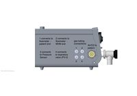
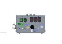
MVM box
- File:Mvm-gas-wiring.pptx.pdf - MVM internals
- File:Mvm-ventillator23b.pdf - gas piping diagram


hw_rev3
Control board
Per board.pdf dated "4/13/20"
- external power supply:
- VLOGIC 24 VDC (up to 40VDC, LM2596, http://www.ti.com/lit/ds/symlink/lm2596.pdf)
- VPOWER ?? VDC (up to 40VDC, LT8609, https://www.analog.com/media/en/technical-documentation/data-sheets/LT8609-8609A-8609B.pdf)
- Adafruit HUZZA32 module (ESP-WROOM32 ESP32 microcontroller ESP32)
- 6 pressure sensors (5525DSO-DB001DS)
- 2 GPIO pins (J5, CH3, CH4, pull up to 3.3V)
- 2 push button inputs (J6, J7 BTN_1, BTN_2, pull up to 3.3V)
- 2 LED drivers (J8, J9 LED, BUZ, 5V)
- 2 "modulation control" (J10, J11)
- 2 "24V solid state relay" (J12, J13, OMRON_G3VM-61FR1)
- 2 I2C 3.3V (J14, J15)
- 2 I2C 5V (J16, J17)
- 1 ESP32 serial console (J18, 3.3V, RX, TX)
- 1 O2 sensor input (J19, OXY_IN)
- 1 SPI 3.3V (J20A)
System configurations
- "Italian model": [ MVM-IT + ESP32 ] ---- usb-serial ---- [ RPi + GUI ] (remote control) ---- wifi or cat5 or SD/USB flash for data collection
- "2.5 Pi": [ MVM-IT + ESP32 --- usb-serial --- RPi + GUI (local control) ] ---- cat5 ---- [ RPi + GUI ] (remote control)
Notable hardware limitations:
- ESP32: yes wifi, no cat5 ethernet, no usb, no sd flash (sd flash maybe via adafruit LCD "feather")
- RPi: cat5/rj45 ethernet, wifi, HDMI/DP, USB, SD flash slot.
Abbreviations: MVM-IT - Italian PCB, ESP32 - adafruit HUZZA32/WROOM32/ESP32 icrocontroller, RPi - RaspberryPi, GUI - medium size LCD running the MVM python GUI
ESP32 connections
!!! ALL GPIO PINS are 3.3V, NOT 5V safe !!!
ESP32 - link to the ESP32 page
- ESP32 power: per https://learn.adafruit.com/adafruit-huzzah32-esp32-feather/power-management, last "not recommended" option: "Connect an external 5V power supply to the USB and GND pins"
ESP32 pin and name - WROOM32 - HUZZA32 - header - schematic name - function

"JP1 16 pin"

42 - GPIO21 - IO21 - 21      - JP1-1  - CS - (output) SPI nCS - mux GPIO21 or VSPIHD
41 - U0TXD  - TXD0 - TX/17   - JP1-2  - TX  - ESP32 console - mux GPIO1 or U0TXD
40 - U0RXD  - RXD0 - RX/16   - JP1-3  - RX  - ESP32 console - mux GPIO3 or U0RXD
38 - GPIO19 - IO19 - MISO/19 - JP1-4  - MISO  - (input) SPI MISO - mux GPIO19 or U0CTS or VSPIQ
35 - GPIO18 - IO18 - MOSI/18 - JP1-5  - MOSI  - (output) SPI MOSI - mux GPIO18 or VSPICLK
34 - GPIO5  - IO5  - SCK/5   - JP1-6  - SCK  - (output) SPI CLK - mux GPIO5 or VSPICS0
24 - GPIO4  - IO4/A2_0 - ADC2/A5/4 - JP1-7  - N/C - mux GPIO4 or RTC_GPIO10
 5 - SENSOR_VP C16/270pF - IO36/SEN_VP/A1_0 - ADC1/A4/36 - JP1-8  - OXY_IN  - (input only)
 8 - SENSOR_VN C17/270pF - IO39/SEN_VN/A1_3 - ADC1/A3/39 - JP1-9  - BTN_2 - mux GPIO39 or RTC_GPIO3 (input only)
10 - VDET_1 - I34/A1_6       - ADC1/A2/34      - JP1-10 - BTN_1 - mux GPIO34 or RTC_GPIO4 (input only)
14 - GPIO25 - IO25/DAC1/A2_8 - ADC2/A1/DAC1/25 - JP1-11 - DAC1 - mux GPIO25 or RTC_GPIO6 or DAC1
15 - GPIO26 - IO26/DAC2/A2_9 - ADC2/A0/DAC2/26 - JP1-12 - DAC2 - mux GPIO26 or RTC_GPIO7 or DAC2
none - none - GND     - JP1-13 - AGND - GND
none - none - NC      - JP1-14 - N/C
none - none - "3V"    - JP1-15 - "3V"
none - none -  RST    - JP1-16 - "RST"

"JP2 12 pin"

none - none - BAT    - JP3-1  - N/C
none - none - EN     - JP3-2  - N/C
none - none - USB    - JP3-3  - "USB" - 5V USB input power
20 - MTCK   - IO13/A2_4 - "red LED" ADC2/13/A12 - JP3-4  - LED - (output) mux GPIO13 or RTC_GPIO14
18 - MTDI   - IO12/A2_5 - "internal pulldown, output only" ADC2/12/A11 - JP3-5  - BUZ - (output) mux GPIO12 or RTC_GPIO15 - "boot fail if pulled high"
16 - GPIO27 - IO27/A2_7      - ADC2/27/A10 - JP3-6  - CH4 - (output) mux GPIO27 or RTC_GPIO17
13 - 32K_XN - IO33/A1_5/X32N - ADC1/33/A9  - JP3-7  - CH3 - (output) mux GPIO33 or RTC_GPIO8
21 - MTDO   - IO15/A2_3      - ADC2/15/A8  - JP3-8  - CH2 - (output) mux GPIO15 or RTC_GPIO13
12 - 32K_XP - IO32/A1_4/X32P - ADC1/32/A7  - JP3-9  - CH1 - (output) mux GPIO32 or RTC_GPIO9
17 - MTMS   - IO14/A2_6      - ADC2/14/A6  - JP3-10 - "BATTERY" - pull up to 3.3V, mux GPIO14 or RTC_GPIO16 (note: ADC2 cannot be used if Wifi active)
39 - GPIO22 - IO22 - SCL/22 - JP3-11 - "SCL" - (I2C, pull up to 3.3V) - mux GPIO22 or U0RTS
36 - GPIO23 - IO23 - SDA/23 - JP3-12 - "SDA" - (I2C, pull up to 3.3V) - mux GPIO23

not on header, internally connected on HUZZA32:

11 - VDET_2 - I35/A1_7 - ADC1/35/A13 - N/C - VBAT voltmeter (through divider) - mux GPIO35 or ADC1_CH7 or RTC_GPIO5 (input only)

not clear what function:

23 - GPIO0   - IO0/A2_1 - GPIO0 - serial RTS - mux GPIO0 or RTC_GPIO11
22 - GPIO2   - IO2/A2_2 - GPIO2 - serial DTR (looks like mistake on schematic) - mux GPIO2 or RTC_GPIO12
25 - GPIO16  - IO16 - IO16 - not connected? - mux GPIO16 or U2RXD
27 - GPIO17  - IO17 - IO17 - not connected? - mux GPIO17 or U2TXD
 9 - CHIP_PU - EN - RESET - push button - no mux

WROOM32 flash memory connection ("U3"):

28 - SD_DATA_2 - SD2 - n/c - mux SD_DATA2 or GPIO9
29 - SD_DATA_3 - SD3 - n/c - mux SD_DATA3 or GPIO10
30 - SD_CMD - CMD - n/c - mux SD_CMD or GPIO11
31 - SD_CLK - CLK - n/c - mux SD_CLK or GPIO6
32 - SD_DATA_0 - SD0 - n/c - mux SD_DATA0 or GPIO7
33 - SD_DATA_1 - SD1 - n/c - mux SD_DATA1 or GPIO8

Not connected to ESP32:

CPU AUX - (maybe output) direct connection to AUX screw terminal

Note:
- I2C controller can use any/all GPIO pins
- SPI controller can use any/all GPIO pins
I2C bus configuration
- ESP32 drives SCL_UC/SDA_UC, connected are:
- U9 "nano dac", part unknown, maybe not installed
- I2C mux TCA9548APWR (A0,A1,A2 tied to GND), output ports:
- 0 - 3V I2C J14
- 1 - 3V I2C J15
- 2 - 5V I2C J16
- 3 - 5V I2C J17
- 4 - PS1 (CSB tied to 3.3V), PS2 (CSB tied to GND)
- 5 - PS3, PS4 (same CSB)
- 6 - PS5, PS6 (same CSB) (maybe absent)
- 7 - N/C
I2C bus addresses
TO BE UPDATED
* 0x70 - I2C switch - U1 - TI TCA9548APWR [[https://edev-group.triumf.ca/hw/ventilator-controller/rev0/-/blob/master/Altium/Datasheets/tca9548a%20-%20I2C%20switch%208-channel.pdf Datasheet]]
* 0x76 - pressure sensor - i2c switch port 7 mask 0x80 - "TE Connectivity Measurement Specialties" 5525DSO-DB001DS [[https://edev-group.triumf.ca/hw/ventilator-controller/rev0/-/blob/master/Altium/Datasheets/MS5525DSO_D20-1%20pressure%20sensor.pdf Datasheet]]
* 0x80 - flow meter - i2c switch port 0 mask 0x01 - SFM3000 - https://gitlab.triumf.ca/mvmdev/mvmcontroller/-/blob/dev-esp32/docs/datasheets/Sensirion-Mass-Flow-Meters-SFM3000-I2C-Functional-Description.pdf https://gitlab.triumf.ca/mvmdev/mvmcontroller/-/blob/dev-esp32/docs/datasheets/Sensirion_Mass_Flow_Meters_SFM3000_Datasheet.pdf https://gitlab.triumf.ca/mvmdev/mvmcontroller/-/blob/dev-esp32/docs/datasheets/SFM3xxx_Extended_I2C_Command_Set.pdf

To probe the pressure sensor:
<pre>
$ i2cset -y 1 0x70 0 0x80
$ i2cget -y 1 0x70
0x80
$ i2cdetect -y 1 ### detects: 0x70 (switch) and 0x76 (pressure sensor)
     0  1  2  3  4  5  6  7  8  9  a  b  c  d  e  f
00:          -- -- -- -- -- -- -- -- -- -- -- -- --
10: -- -- -- -- -- -- -- -- -- -- -- -- -- -- -- --
20: -- -- -- -- -- -- -- -- -- -- -- -- -- -- -- --
30: -- -- -- -- -- -- -- -- -- -- -- -- -- -- -- --
40: -- -- -- -- -- -- -- -- -- -- -- -- -- -- -- --
50: -- -- -- -- -- -- -- -- -- -- -- -- -- -- -- --
60: -- -- -- -- -- -- -- -- -- -- -- -- -- -- -- --
70: 70 -- -- -- -- -- 76 --
hw_rev4
Control board
TBW, waiting for board schematics
System architecture
valves, sensors ---i2c--- ESP32 ---esp32-u0-serial---serial-usb-bridge-|---usb-cable---|---RPi4B---|---LCD screen

sensors,etc ---i2c--- "supervisor microcontroller" --- connected to TBW, waiting for board schematics
ESP32 connections
!!! ALL GPIO PINS are 3.3V, NOT 5V safe !!!
ESP32 - link to the ESP32 page
TBW, waiting for board schematics
I2C bus configuration
- ESP32 drives SCL_UC/SDA_UC, connected are:
TBW, waiting for board schematics
I2C bus addresses
TBW, waiting for board schematics
Pressure sensor
Calibration constants (chip on KO's board):
read by i2cget (addr 0xa0 through 0xae)
pi@raspberrypi:~ $ i2cget -y 1 0x76 0xa0 w
0x0100
read by sensors.exe (branch dev-linux)
pressure sensor PROM 0x00: 0x0001
pressure sensor PROM 0x01: 0x392b
pressure sensor PROM 0x02: 0x1e52
pressure sensor PROM 0x03: 0x0e25
pressure sensor PROM 0x04: 0x071a
pressure sensor PROM 0x05: 0x943d
pressure sensor PROM 0x06: 0x1f6b
pressure sensor PROM 0x07: 0x000c
mvm_hal_init: PS1 CRC4 OK!
- read ADC, no conversion
root@raspberrypi:~/i2c-tools-4.1/tools# ./i2cget3 -y 1 0x76 0
write returned 1
read returned 4, value 0x3f000000
- read ADC, pressure
i2cset -y 1 0x76 0x48
root@raspberrypi:~/i2c-tools-4.1/tools# ./i2cget3 -y 1 0x76 0
write returned 1
read returned 4, value 0x3f900a44
- read ADC, temperature
i2cset -y 1 0x76 0x58
root@raspberrypi:~/i2c-tools-4.1/tools# ./i2cget3 -y 1 0x76 0
write returned 1
read returned 4, value 0x3f9c424d
Flow sensor
TBW
Proportional Valve ArduinoCorePP_PWM_hw_v3 firmware
- From Bryerton:
The Italian's use the PWM on DAC1 / A0 / IO25 pin. The API is the ledc API used to control an LED via PWM
- see ArduinoCorePP_PWM_hw_v3.ino
- function setup() attach pin "DAC1" to ledc
ledcSetup(0, 10000, 12); // KO: chan 0, freq in kHz, how many bits of PWM 12 bits = range 0..4095
ledcAttachPin(DAC1, 0); // KO: IO25/A0/DAC1
ledcWrite(0, 0);
- function PressureControlLoop_PRESSIN() see ledcWrite()
if (Pset == 0) {
  ledcWrite(0, 0);
} else {
  pid_outb = ...; // KO: looks like a digital PID controller
  if (pid_outb<0) pid_outb=0; // KO: low limit
  pid_outb = pid_outb + 500; // KO: what is this?!?
  if (pid_outb>4090) pid_outb=4090; // KO: high limit
  ledcWrite(0, pid_outb); // KO: value 500..4090
}
- also see valve_control() commented absent code for PWM.
MVM-GUI
Code review
- pdoc diagrams - https://home.fnal.gov/~mwang/mvm/sqa/gui/html/index.html
Install
- as root:
- apt-get update
- apt-get install python3-pyqt5 python3-numpy python3-pyqtgraph python3-serial
- ### does not work, installs wrong pip: apt-get install python3-pip
- curl https://bootstrap.pypa.io/get-pip.py -o get-pip.py
- python3 get-pip.py --force-reinstall
- ### does not work, installs too-old version of yaml 3.13: apt-get install python3-yaml
- pip3 install PyYAML ### version 5.3.1
- ssh pi@rpi
- git clone https://github.com/MechanicalVentilatorMilano/gui.git
- #git clone https://gitlab.triumf.ca/mvmdev/gui.git
- #git checkout ko_test
Run with python simulator
- cd gui
- ./mvm_gui.py fakeESP32
Run with ESP32 simulator
- load the ardiuno sketch mock/mock.ino into ESP32 (see instructions below)
- ./mvm_gui.py ### default connection is /dev/ttyUSB0 at 115200 bps, change it in default_settings.yaml
MVMFirmware monolithic hw_rev3, hw_rev4
Prepare
- install arduino: https://daq.triumf.ca/DaqWiki/index.php/ESP32#Arduino_IDE
Build and Flash
- ssh pi@...
- ### use TRIUMF gitlab branch ko_test instead ### git clone https://github.com/NuclearInstruments/MVMFirmware.git
- git clone https://gitlab.triumf.ca/mvmdev/MVMFirmware.git
- git checkout ko_test
- cd arduino; ./ardiuno
- open .../MVMFirmware/ArduinoCorePP_PWM_hw_v3/ArduinoCorePP_PWM_hw_v3.ino
- install library SimpleCLI (1.0.9), aREST (2.8.0)
- build sketch (there is warnings about TwoWire::requestFrom())
- load sketch
Connect and Use manually
- use Ardiuno tools -> serial console, set: serial 115200
- or use minicom, set /dev/ttyUSB0, 115200 bps, no flow control
- output on a base esp32 (no baseboard, no hardware, no sensors, etc)
ets Jun  8 2016 00:22:57

rst:0x1 (POWERON_RESET),boot:0x13 (SPI_FAST_FLASH_BOOT)
configsip: 0, SPIWP:0xee
clk_drv:0x00,q_drv:0x00,d_drv:0x00,cs0_drv:0x00,hd_drv:0x00,wp_drv:0x00
mode:DIO, clock div:1
load:0x3fff0018,len:4
load:0x3fff001c,len:1044
load:0x40078000,len:8896
load:0x40080400,len:5816
entry 0x400806ac
SCAN I2C BUS: 0
Scanning... I2C
No I2C devices found

SCAN I2C BUS: 1
Scanning... I2C
No I2C devices found

SCAN I2C BUS: 2
Scanning... I2C
No I2C devices found

SCAN I2C BUS: 3
Scanning... I2C
No I2C devices found

SCAN I2C BUS: 4
Scanning... I2C
No I2C devices found

SCAN I2C BUS: 5
Scanning... I2C
No I2C devices found

SCAN I2C BUS: 6
Scanning... I2C
No I2C devices found

SCAN I2C BUS: 7
Scanning... I2C
No I2C devices found

SENSOR:           0
SENS_T1:          65535
OFF_T1:           65535
TCS:              65535
TCO:              65535
TREF:             65535
TEMPSENS:         65535
OFFSET:            0.00
SENSOR:           1
SENS_T1:          65535
OFF_T1:           65535
TCS:              65535
TCO:              65535
TREF:             65535
TEMPSENS:         65535
OFFSET:            0.00
SENSOR:           2
SENS_T1:          65535
OFF_T1:           65535
TCS:              65535
TCO:              65535
TREF:             65535
TEMPSENS:         65535
OFFSET:            0.00
SENSOR:           3
SENS_T1:          65535
OFF_T1:           65535
TCS:              65535
TCO:              65535
TREF:             65535
TEMPSENS:         65535
OFFSET:            0.00
SFM driver version 0.1.0
SFM sensor probing failed
...
Measure Flow Sensor initialized!
- send: "get all", reply: "valore=0.00,0.00,0,0,0,0,0,0,1"
Connect and read data using mvm-control
Follow the README file at: https://github.com/MechanicalVentilatorMilano/mvm-control
MVMFirmwareCpp
Prepare
- install arduino: https://daq.triumf.ca/DaqWiki/index.php/ESP32#Arduino_IDE
Build and Flash
- ssh pi@...
- git clone git@github.com:NuclearInstruments/MVMFirmwareCpp.git
- cd arduino; ./ardiuno
- open .../MVMFirmwareCpp/MVMFirmwareCore/MVMFirmwareCore.ino/ArduinoCorePP_PWM_hw_v3
- install library SimpleCLI (1.0.9)
- build sketch
- if there is error about missing arduino.h, create one with this contents in the same directory as the .ino file
// arduino.h
#include <Arduino.h>
- upload sketch into esp32
Connect and Use manually
- use Ardiuno tools -> serial console, set: serial 115200
- or use minicom, set /dev/ttyUSB0, 115200 bps, no flow control
- output on a base esp32 (no baseboard, no hardware, no sensors, etc)
...
- send: "get all", reply: "valore=..."
Connect and read data using mvm-control
Follow the README file at: https://github.com/MechanicalVentilatorMilano/mvm-control
- git clone https://github.com/MechanicalVentilatorMilano/mvm-control.git
- cd mvm-control
- python mvm_control.py -p /dev/ttyUSB0 log
{"time":1.717,"p_patient":0.00,"f_total":0.00,"o2":100.00,"bpm":0.00,"v_total":0.00,"peep":0.00,"temp":0.00,"bat_pwr":1,"bat_charge":100.00,"p_peak":0.00,"v_total_insp":0.00,"v_total_exhl":0.00,"f_peak":0.00},
...
Connect with mvm_gui
See below for instructions to install mvm_gui
- cd gui/gui
- ./mvm_gui.py
Firmware to GUI interface
Physical link
USB serial, 115200 bps
Set commands
(as of commit Sun Apr 19 13:44:21 2020 +0200 ed0e7758193d0bdcff982ad073c7e35eefbb2273)
- "run"
- "mode"
- "rate"
- "ratio"
- "assist_ptrigger"
- "assist_flow_min"
- "ptarget"
- "pressure_support"
- "peep"
- "pid_p"
- "pid_i"
- "pid_d"
- "pid_p2"
- "pid_i2"
- "pid_d2"
- "pause_inhale"
- "pause_lg"
- "pause_lg_time"
- "pause_lg_p"
- "pause_exhale"
- "pid_limit"
- "alarm_snooze"
- "alarm"
- "watchdog_reset"
- "console"
- "timestamp"
- "wdenable"
- "backup_enable"
- "backup_min_rate"
- "stats_clear"
- "pcv_trigger_enable" - hw_v4
- "pcv_trigger" - hw_v4
Get commands
- "pinput" - hw_v4
- "pressure"
- "flow"
- "o2"
- "bpm"
- "backup"
- "tidal"
- "peep"
- "temperature"
- "power_mode"
- "battery"
- "version"
- "alarm"
- "warning"
- "run"
- "mode"
- "rate"
- "ratio"
- "assist_ptrigger"
- "assist_flow_min"
- "ptarget"
- "pressure_support"
- "backup_enable"
- "backup_min_rate"
- "all"
- "calib"
- "calibv"
- "calib_o2" - hw_v4 20apr2020
- "stats"
- "pause_lg"
- "pause_lg_time"
- "pause_lg_p"
- "ads" - hw_v4
- "pcv_trigger_enable" - hw_v4
- "pcv_trigger" - hw_v4
get all
- commit Sun Apr 19 13:44:21 2020 +0200
hw_v3:
if (strPatam == "all") {
        Serial.println("valore=" + String(pressure[1].last_pressure) + "," + String(tidal_volume_c.FLUX) + "," + String(last_O2) + "," + String(last_bpm)
            + "," + String(tidal_volume_c.TidalVolume * VOL_COMP) + "," + String(last_peep)
            + "," + String(temperature) + "," + String(batteryPowered ? 1 : 0) + "," + String(currentBatteryCharge)
            + "," + String(currentP_Peak)
            + "," + String(currentTvIsnp * VOL_COMP)
            + "," + String(currentTvEsp * VOL_COMP)
            + "," + String(currentVM));
    }
hw_v4:
    if (strPatam == "all") {
        Serial.println("valore=" + String(pressure[1].last_pressure) + "," + String(tidal_volume_c.FLUX) + "," + String(last_O2) + "," + String(last_bpm)
            + "," + String(tidal_volume_c.TidalVolume * VOL_COMP) + "," + String(last_peep)
            + "," + String(temperature) + "," + String(batteryPowered ? 1 : 0) + "," + String(currentBatteryCharge)
            + "," + String(currentP_Peak)
            + "," + String(currentTvIsnp * VOL_COMP)
            + "," + String(currentTvEsp * VOL_COMP)
            + "," + String(currentTvIsnp * VOL_COMP * last_bpm/1000.0));
    }
get alarm
returns uint32_t ALARM_FLAG, following bits are defined: (hw_v3, hw_v4, V5)
Alarms bits are set from TriggerAlarm(enum t_ALARM):
List t_ALARM values:
PRESSURE_DROP_INHALE, // not used hw_v3, hw_v4, V5
UNABLE_TO_READ_SENSOR_PRESSURE, // loop() read_pressure_sensor(0,1) != 0
// "V5" HAL.cpp !drv_Ploop.asyncMeasure() || !drv_PPatient.asyncMeasure()
UNABLE_TO_READ_SENSOR_FLUX, // loop() MeasureFlux() != 0 || MeasureFlux_SFM3019() != 0
// "V5" HAL.cpp !drv_FlowIn.doMeasure()
UNABLE_TO_READ_SENSOR_VENTURI, // loop() read_pressure_sensor(2) != 0
// "V5" HAL.cpp !drv_PVenturi.asyncMeasure()
ALARM_COMPLETE_OCCLUSION, // CheckAlarmConditions() - commented out
// "V5" TransitionInhaleExhale_Event()
ALARM_PARTIAL_OCCLUSION, // CheckAlarmConditions() - commented out
// "V5" TransitionInhaleExhale_Event()
ALARM_PRESSURE_INSIDE_TOO_HIGH, // CheckAlarmCondition() pressure[0].last_pressure > 50
// "V5" CheckStaticAlarms() pPatient > 50 || pLoop > 65
ALARM_PRESSURE_INSIDE_TOO_LOW, // CheckAlarmCondition() pressure[0].last_pressure < 0.5 * core_config.target_pressure
// "V5" TransitionInhaleExhale_Event() pLoop < 0.5 current_pressure_setpoint
ALARM_LEAKAGE, // CheckAlarmConditions() pressure[1].last_pressure < 0.8 * core_config.target_pressure
// "V5" TransitionInhgaleExhale_Event() pPatient < 0.8 * current_pressure_setpoit
BATTERY_LOW, // CheckAlarmConditions() if currentBatteryCharge < 20
// "V5" (currentBatteryCharge < 20) && batteryPowered
ALARM_PRESSURE_INPUT_TOO_LOW, // not used
// "V5" HAL.cpp (InputValveValue > 0) && (Pin < MIN_PIN) (MIN_PIN=3000)
ALARM_PRESSURE_INPUT_TOO_HIGH, // not used
// "V5" HAL.cpp Pin > MAX_PIN (MAX_PIN=4500)
ALARM_GUI_ALARM, // command "set alarm"
// "V5" SetAlarmGUI(bool), cleared by "set alarm 0" and "alarm_snooze 29", set by "set alarm 1"
ALARM_GUI_WDOG, // loop() millis() > watchdog_time + 5000
// "V5" CheckStaticAlarms() wdog_timer > 6000
ALARM_OVER_UNDER_VOLTAGE, // "V5" HAL.cpp (adc_channel==2 VoltageProbe12V < 10 || > 15) || (adc_channel==3 VoltageProbe5V < 4.7 || > 5.3)
ALARM_SUPERVISOR, // "V5" HAL.cpp SuperVisorAlarms != 0
ALARM_OVERTEMPERATURE, // "V5" HAL.cpp BoardTemperature > 75
ALARM_APNEA, // "V5" state machine "dt / 1000.0 > core_config->backup_min_rate"
UNPREDICTABLE_CODE_EXECUTION // onTimerCoreTask()
// "V5" SMexecute()
Alarm bits:
#define __ERROR_INPUT_PRESSURE_LOW 0 // ALARM_PRESSURE_INPUT_TOO_LOW
#define __ERROR_INPUT_PRESSURE_HIGH 1 // ALARM_PRESSURE_INPUT_TOO_HIGH
#define __ERROR_INSIDE_PRESSURE_LOW 2 // ALARM_PRESSURE_INSIDE_TOO_LOW
#define __ERROR_INSIDE_PRESSURE_HIGH 3 // ALARM_PRESSURE_INSIDE_TOO_HIGH
#define __ERROR_BATTERY_LOW 4 // BATTERY_LOW
#define __ERROR_LEAKAGE 5 // PRESSURE_DROP_INHALE || ALARM_LEAKAGE
#define __ERROR_FULL_OCCLUSION 6 // ALARM_COMPLETE_OCCLUSION
#define __ERROR_PARTIAL_OCCLUSION 7 // ALARM_PARTIAL_OCCLUSION
#define __ERROR_APNEA 22 // "cpp" ALARM_APNEA
#define __ERROR_ALARM_PI 29 // ALARM_GUI_ALARM
#define __ERROR_WDOG_PI 30 // ALARM_GUI_WDOG
#define __ERROR_SYSTEM_FALIURE 31 // UNABLE_TO_READ_SENSOR_PRESSURE || UNABLE_TO_READ_SENSOR_FLUX || UNABLE_TO_READ_SENSOR_VENTURI || UNPREDICTABLE_CODE_EXECUTION
bit ERROR_ALARM_PI:
- set by ALARM_GUI_ALARM from command "set alarm"
- cleared by ResetAlarm()
- cleared by command "set wdenable"
bit ERROR_WDOG_PI:
- set by ALARM_GUI_WDOG from loop() if millis() > watchdog_time + 5000
- cleared by command "set watchdog_reset"
- watchdog_time is set in setup() and by command "set watchdog_reset"
Watchdog
- watchdog gui to esp32 (esp32 alarm if gui crash)
- watchdog esp32 to gui (gui alarm if esp32 crash)
Display Unit
SD image MvM_raspPi4_16gb_new.7z (14-Apr-2020)
-rw-r--r--@ 1 8ss  staff   5161636360 Apr 16 09:52 MvM_raspPi4_16gb_new.7z
-rwxr-xr-x  1 8ss  staff  15931539456 Apr 14 06:02 MvM_raspPi4_16gb_new.img

8s-macbook-pro:NOBACKUP 8ss$ shasum -a 256 MvM_raspPi4_16gb_new.*
91987742cbf2c810afa74a47455a21de5b75b85c4fa134c10f48a30afae64194  MvM_raspPi4_16gb_new.7z
bc5ed0efa279b027da4965132c91f494363ea98a297a649a062f346760d5de2e  MvM_raspPi4_16gb_new.img
On power up:
- boots Raspbian 10 Buster
- starts X11 (in the alt-shift-f7 console)
- starts python3 gui (lightdm -> lxsession -> /home/pi/gui.sh -> /home/pi/work/MVMSoftware/gui/gui/mvm_gui.py)
- if no ESP32 connected, displays an "abort, retry, ignore" dialog
- if ESP32 connected, displays nothing (hung? wrong ESP32 firmware?)
- starts TeamViewer (from systemd)
- user pi is logged in the alt-shift-f1 console (no password) (via systemctl autologin agetty?)
Autologin:
- lightdm: /etc/lightdm/lightdm.conf has this "autologin-user=pi"
- lxsession: /home/pi/.config/lxsession/LXDE-pi/autostart has this: "@/home/pi/gui.sh"
- /etc/systemd/system/autologin@.service has this: "ExecStart=-/sbin/agetty --autologin pi --noclear %I $TERM"
Partitions mounted:
- / (mmcblk p7)
- /boot (mmcblk p6)
Running processes:
- ModemManager (this is a mistake, it will fight over access to /dev/USB0)
- TeamViewer (is this secure, what's the access password?)
- no sshd
- no NetworkManager
Users:
- root, password blank (login disabled)
- pi, password raspberry (default password)
Network:
- eth0 RJ45 - DHCP is enabled, gets an IP address
- wlan0 (radio is on, per rfkill) - configured to connect to 3 wifi networks (2 of them maybe disabled)
- bluetooth (radio is on, per rfkill) - looks to be on, not clear if paired with anything
SD Partition table:
Disk /dev/sda: 29.3 GiB, 31486640128 bytes, 61497344 sectors
Disk model: STORAGE DEVICE
Units: sectors of 1 * 512 = 512 bytes
Sector size (logical/physical): 512 bytes / 512 bytes
I/O size (minimum/optimal): 512 bytes / 512 bytes
Disklabel type: dos
Disk identifier: 0x000d0750

Device     Boot   Start      End  Sectors  Size Id Type
/dev/sda1          8192  5015625  5007434  2.4G  c W95 FAT32 (LBA)
/dev/sda2       5015626 31116287 26100662 12.5G  5 Extended
/dev/sda5       5021696  5087229    65534   32M 83 Linux
/dev/sda6       5087232  5611517   524286  256M  c W95 FAT32 (LBA)
/dev/sda7       5611520 31116287 25504768 12.2G 83 Linux
root@raspberrypi:/mnt/tmp/home/pi#
SD partition contents:
- sda1: looks like RPi recovery partition (what is this?)
- sda2: extended partition (why?)
- sda5: (what is this?)
- sda6: boot partition, cmdline.txt has "console=serial0,115200 console=tty1 root=/dev/mmcblk0p7 rootfstype=ext4 elevator=deadline fsck.repair=yes rootwait quiet splash plymouth.ignore-serial-consoles"
- sda7: "/" including /home/pi.