Barrel Scintillator
Back to Main Page
Table of Figures
Purpose
Antihydrogen annihilation identification in ALPHA crucially depends on the software capability to reject background events, i.e., cosmic rays. Given that the ALPHA-g detectors offer more information than what was available in ALPHA, new and more sophisticated algorithms will be developed to remove backgrounds events. Two types of tools will be deployed: “online” software aimed to monitor antihydrogen production and “machine learning algorithms” to eliminate background from the physics measurements.
While this software will provide the necessary rejection of the cosmic rays, the information collected for making this decision is based on a "Barrel Scintillator" layer surrounding the Radial TPC. Particles traversing this detector will leave a track of light which is recorded in time and intensity. The time correlation between different parts of the Barrel Scint. will permit the identification of the source of the particle.
Scope
Design of the Barrel Scintillator
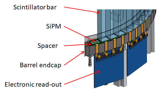
The barrel scintillator is constituted of 64 scintillators bars and forms a barrel which surround the TPC. The following picture present the design of this barrel.
This cylinder is literally a barrel due to the fact that each bar has a trapezoidal section. This reinforce naturally the structural resistance and stability of the cylinder. The amount of bar (64) is a compromised between the acceptable quantity of data, and the azimuth (φ) resolution. The length of each bar is 2.6 meter which is enough to cover the whole 2.4 meter TPC.
Light collection
The scintillators bars are made from EJ200 plastic scintillator from the Texan company Eljen Technology ([Eljen2016]). A particle crossing this scintillator will produce light whose the wavelength is centered around 425 nm. This light is emitted in all direction and reach the Silicone PhotoMultiplier(SiPM) applied on each side of each bar. The silicone Photomultipliers are the 6x6mm MicroFJ-60035 from the company SensL ([SensL2015]). The wavelength of the photon Detection Efficiency peak for these sensors is 420 nm, which correspond to the light emitted by the scintillator. Furthermore these sensors are bias with a low voltage (-30V) and have a small thickness (about 1mm) which make easier their integration in the read-out of the barrel scintillator.
Between the edge of the scintillator bar and the SiPM, a thin thickness (about 1-2 mm) of a transparent silicone rubber have been add in order to prevent any air gap. This silicone rubber is the RTV 615 product with 5% of hardener (by mass) which is commonly used to couple the photo-multipliers tubes to light guides. Previous tests have shown an increase of 30% in the light transmitted to the SiPM with this silicone rubber, in comparison with a set-up without any coupling material. 6 SiPMs are used for the read-out of the light of each edge of the bars. This means approximately 50% of the edge is covered by SiPM. This choice is a compromised between the space constraints (enough space have to be kept to support the weight of each bar), and the fact that the more the light is receive, the better the time resolution is.
Electronic read-out
Overview
The goal of the electronic read-out of the barrel scintillator is to determine the time difference between the signals reaching the two opposite sides of a scintillator bar. Knowing this time difference, it is so possible to calculate the position of each events in the barrel, track the particles if several bars produce a signal, and determine if the event is due to a cosmic ray or an annihilation.
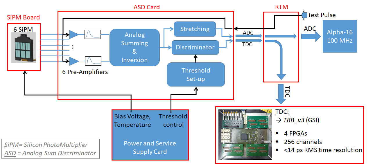
The calculation of the time difference is assured by a Time to Digital Converter (TDC), the TRB_V3 from GSI, which include 5 FPGAs, 256 channels and is able to measure a time with a resolution inferior to 14 ps ([Korcyl 2018]). To achieve the goal of the barrel scintillator, the time difference have to be calculated with a resolution of an order of 200 ps.
Some parts of the waveform of the SiPM signals are recorded too, in order to calculate a time correction based on the amount of photons received by the SiPM. This is ensured by an Analog to Digital Converter (ADC), the Alpha-16 card which support a 100 MHz channel. In order to produce these data, several electronic cards have been designed:
- - The SiPM board: which support the 6 SiPM for each side of the scintillators bars.
- - The ASD card: ASD stand for Analog Sum Discriminator. This card receive the analog signal from the 6 SiPM amplify and sum these signals. And produce an analog and a digital signal respectively for the ADC and the TDC.
- - The Rear Transition Module (RTM), which distribute the signals to the ADC and the TDC.
- - The Power Distribution Card, which supply the voltage and the threshold level of the discriminator for the ASD card.
All of these parts appears in the following schematic.
On the ASD card, the signals of the 6 SiPM are amplified and sum in order to get a signal of an order of one or two volts. This signal is then used to feed a discriminator stage as well as a stretching stage.
TDC signal
The discriminator stage generate an LVPECL signal each time the sum of the six SiPM reach a certain threshold. This threshold is generated by a Digital to Analog Converter (DAC) which is monitored from the Power Distribution Card. The resolution of this threshold is of an order of a photo-electron volts, which allow the discriminator to detect low amplitude signals which are just above the dark noise. The LVPECL signal is converted in an LVDS signal on the Rear Transition Module (RTM). As there is about 8 meters of cable between the ASD card and the TDC, this allow to generate a clean and sharp signal right before the TDC. Previous test realized with this electronic and with cosmic ray events in the middle of the bar have shown a time difference resolution of an order of 160 ps without any time correction.
ADC signal
The waveform of the six SiPM sum is used to calculate a time correction as well, based on an estimation of the amount of photon reaching the SiPMs. This estimation might be realized with the area under the waveform, which is proportional to the charge of the SiPM; however for important amount of photon, the signal will probably be saturated. The other way is to look at the beginning of the rising edge of the signal. Thus, in order to have a sufficient resolution in this particular area, the signal is stretched before reaching the 100 MHz ADC.
Definitions and Abbreviations
General acronyms or terms used for the ALPHA-g experiment
| rTPC | Radial Time projection Chamber |
| z | Coordinate along the main axis of the trap and rTPC |
| φ | Azimuthal coordinate, φ = 0 is in direction of cartesian x |
| θ | Angle towards the z-axis |
| r | Radial coordinate in the cylindrical rTPC system |
| pφ | φ component of the pion's original momentum |
| pθ | θ component of the pion's original momentum |
| GEANT4 | GEometry ANd Tracking, particle physics simulation package |
| Garfield++ | Gas detector simulation package |
Table 1 – ALPHA-g Abbreviations
References and Related Documents
| Eljen 2016 | Eljen Technology, “General Purpose Plastic Scintillator EJ-200, EJ-204, EJ-208, EJ-212”, January 2016. |
| Korcyl 2018 | Grzegorz Korcyl, Ludwig Maier, Jan Michel, Andreas Neiser, Marek Palka, Manuel Penschuck, Pawel Strzempek, Michael Traxler, Cahit Ugur, “A Users Guide to the TRB3 and FPGA-TDC Based Platforms”, March 2018. |
| SensL 2015 | SensL, “J-Series High PDE and Timing Resolution, TSV Package – Datasheet”, 2015. |
Studies
Timing resolution
The time resolution is an important factor in the barrel scintillator acquisitions and is directly linked to the capability of the barrel to act as a veto, ie. to discriminate the events coming from outside (from cosmic rays) to the events coming from inside the barrel (annihilation of anti-particle).
The time which matter in this chapter is the difference of time between the signals generated by each side of one bar, when a particle cross the bar and produce an event. Some of the factors involved in this time resolution are:
- - The decay time of the scintillator: all the photons are not generated at the same time but following a law with a constant decay (equal to 2.1 ns for the EJ200 scintillator plastic).
- - The reflections of the photons inside the bars which delayed the time of arrival of some photon.
- - The variation in the amount of photon generated for each event. This influence the shape and the rising time of the analog signal generated by the SiPM, and so the measured time of arrival.
- - The jitter of the electronics components propagating the signal up to the TDC.
- - The data analysis.
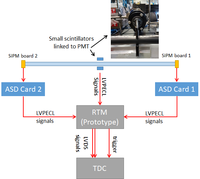
To experimentally measure the time resolution it is although important to be as close as possible to the final read-out design. In the experiment made at Triumf, a bar of the future barrel scintillator was used, as well as the final SiPM board, a prototype of the ASD card, the final cables (type and length), and the TDC which will be used for the ALPHA-g experiment.
For this experiment, smaller scintillators (linked to PMT) were used to trigger the TDC and look at the events generated in the middle of the bar only. The following schematic described the set-up of the experiment:
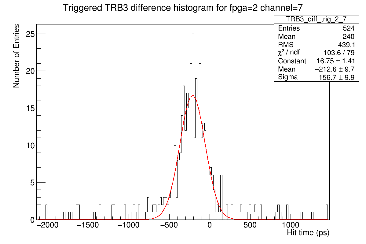
In this experiment, the sigma of the time difference measured with the TDC is equal to 157 ps. This result appears on the following figure.
The goal for this experiment was to reach 200 ps of time resolution, although this result meet the timing requirement to use the barrel scintillator as a veto.
Amplitude correction
Mechanical structure
Description dwg, assembly


