VF48
VF48 - 48 channels@60Msps, 10bits
Links
- firmware repository: https://bitbucket.org/ttriumfdaq/vf48/src/master/
- schematics: https://bitbucket.org/ttriumfdaq/vf48/src/master/doc/VF48_opj%20-Restored.pdf
- VME flash programmer and VME tools: https://bitbucket.org/ttriumfdaq/vme/src/master/
General characteristics
The VF48 is a one-unit wide VME 6U housing 48 channels digitized by six fast 10-bit ADCs. For each channel, the input signal (50 Ω impedance) is amplified by a high speed differential amplifier (AD8132) and them converted by the ADCs at a maximum rate of 60 Msps.
The digitized signal goes to a FPGA (Cyclone EPC12) which will calculate the charge of the signal, evaluate the exact trigger time, build an event which will contain all this information and send the event constructed to a local collector. Each FPGA manages eight channels. There are six FPGA connected to the ADCs and one FPGA which collects the data.
The board can be accessed in A24 addressing mode, D32, BLT32, MBLT64 and 2eVME data transfer mode. (max data rate around 40-50 Mbytes/sec)
It has also a board available to access the VF48 throw a LVDS link. This link can transfer the data at a speed up to 100 Mbits/s. This link can afford all the control necessary to run the VF48. It can accept a clock which permits the synchronization of many VF48 units.
The board contains a trigger structure which permits to trigger the data in three different manners. The trigger can come from an external NIM signal, from a software command or from an internal mechanism. The internal mechanism manages multiple channels hit, deadtime, threshold and multiplicity and is totally programmable by the user.

Power use
VF48 power use with firmware ???:
VF48        sn12      sn70
preamps: AD8132 AD8137
+5V         3.7A      4A
+12V        0.5A      0.1A
-12V        0.6A      0.2A
LEDs, jumpers, switches and connectors
Front panel items
- RED LED : FPGA configured - if red led is off, one or more FPGAs did not configure, maybe because of empty or corrupted flash memory
- YELLOW LED : state of the S8 NIM termination switch (off means termination is off)
- GREEN LED : when running - repeats the AUX OUT signal; when idle - VME access LED
- H_RST : push button to reset and reconfigure all FPGAs (if reset-mod is installed)
- CLK IN-OUT LEMO : NIM clock pass-through (can be daisy chained)
- TRIG IN-OUT LEMO : NIM external trigger pass-through (can be daisy chained)
- RESET IN-OUT LEMO : what does it do ?!?
- AUX IN LEMO : what does it do ?!?
- AUX OUT LEMO : selectable NIM output function (internal busy, clock output, trigger output, etc)
- RJ45 : TIGC connection (use CAT6 cable)
- 3x17 pin headers : analog inputs (input ordering for recent firmware versions has channel 0 on the very bottom of the module).
Clock selector jumpers
Jumpers S6 and S7 control VF48 clock selection. Valid settings are:
- local clock (normal position): set S7 to "S6 selector enabled" (low position), set S6 to "local clk" (upper position)
- NIM clock: set S7 to "S6 selector enabled" (low position), set S6 to "nim clk" (lower position)
- RJ45 clock: set S7 to "RJ45 clock" (upper position)
VME base address switch
Four-switch block S10 is used to set the VME base address. On most VF48 modules, the bit order on this switch block is reversed - the correct bit order is - bit 0 - next to label "ID0" closer to the VME connector, bit 3 - away from the VME connector.
FPGA connectors
- J2 is the JTAG connector (7 Cyclone-1 FPGA units: collector first, then frontend 5 through frontend 0)
- J3 is the AS (active serial) connector for programming flash memory
VME interface
The VF48 board decodes these VME address modifiers (AM):
| VME AM | Description |
|---|---|
| 3F | A24 supervisory block transfer (BLT32) |
| 3D | A24 supervisory data access |
| 3C | A24 supervisory 64-bit block transfer (MBLT64) |
| 3B | A24 non privileged block transfer (BLT32) |
| 39 | A24 non privileged data access |
| 38 | A24 non privileged 64-bit block transfer (MBLT64) |
Base Address
The VME base address of the VF48 module is 0xA00000 + n*0x10000, where n is set by the S10 switch: 0xA00000, 0xA10000 through 0xAF0000.
The VF48 module decodes 64 kibytes of VME A24 address space: 0x00An0000 to 0x00AnFFFF.
Note that on most VF48 modules, the labeling of S10 VME base address jumper block is incorrect. Bit 0 of module ID is the one labeled ID0 - the nearest to the VME connector and bit 3 is the farthest from the VME connector.
Data Transfer Capabilities
Access to control registers should be done using A24/D32 cycles. Access to the data FIFO should be done using A24 BLT32/MBLT32/2eVME cycles.
VF48 Collector VME registers
VME registers
| Offset | Name | Access | Description |
|---|---|---|---|
| 0x000X | CSR | R/W | |
| 0x001X | SSCSR | W | |
| 0x002X | TestReg | R/W | |
| 0x003X | Firmware ID | R | |
| 0x0040,1 | SoftReset | W | |
| 0x0044,5 | Nframes(Also A0) | R | |
| 0x005X | Param DAT | W | |
| 0x006X | Param ID | W | |
| 0x007X | Software Trigger | W | |
| 0x008X | LVDS Reset | W | |
| 0x009X | Group Enable | R/W | |
| 0x00AX | NFrames | R | |
| 0x00BX | General Reset | W | |
| 0x00CX | Trigger Config A | R/W | |
| 0x00DX | Trigger Config B | R/W | |
| 0x00EX | Active-Serial Flash Programmer | R/W | |
| 0x00FX | unused | R/W | ... |
| 0x0100 | LVDS link monitor A | R | LinkMon[31..0] (frontends 0,1,2,3) |
| 0x0110 | LVDS link monitor B | R | LinkMon[63..32] (frontends 4 and 5) |
| 0x0120 | FE0,1 FIFO status | R | ... |
| 0x0130 | FE2,3 FIFO status | R | ... |
| 0x0140 | FE4,5 FIFO status | R | ... |
| 0x0150..1A0 | FIFO 0..5 data | R | ... |
| 0x01B0 | FE 0,1 receive word count | R | ... |
| 0x01C0..1E0 | RT signals from FE 0..5 | R | ... |
| 0x01F0 | digital sum trigger threshold | R/W | ... |
| 0x0200 | RT signal to TIGC | R | ... |
| 0x1XXX..FFFF | Event Data | R | D32/BLT32/MBLT64/2eVME/2eSST (2eSST requires hardware mod) |
CSR Description
| Bit | Name | Access | Quartus Name | Discussion | |
|---|---|---|---|---|---|
| 0 | 0x0001 | Run | R/W | RUN | The RUN bit allows the system to accept triggers and start the acquisition. |
| 1 | 0x0002 | Parameter ID Ready | R | The Parameter ID Ready bit and Parameter DAT Ready bit indicate if parameter is ready to be read. The parameter section will describe more precisely how these bits work. | |
| 2 | 0x0004 | Parameter DATA Ready | R | ||
| 3 | 0x0008 | Event Fifo Empty | R | fifo_empty | This bit drops from 1 to 0 when data is available for reading from the data FIFO. The "Nframe" VME register contains the number of 32-bit words that can be read from the FIFO. Sometimes "Nframe" is non-zero but "fifo_empty" is set to 1 indicating an emepty fifo - this means that some data did arrive into the VF48 collector but is not yet available for reading from the VME FIFO. Please wait until "fifo_empty" goes to 0 before reading the data. |
| 4 | 0x0010 | Event Fifo Incomplete | R | fifo_incomplete | The Event Fifo does not have a complete event - some frontends did not receive the end of event yet. |
| 5 | 0x0020 | ||||
| 6 | 0x0040 | TIGC_Config[0] | |||
| 7 | 0x0080 | External Trigger | R/W | Select_ExtTrigger | Set to 1 to trigger from NIM Trigger input, set to 0 to trigger from the self-trigger (Grand-OR or Multiplicity) or from the TIGC trigger (see section on VF48 Trigger functions) |
| 8 | 0x0100 | ||||
| 9 | 0x0200 | ||||
| 10 | 0x0400 | ||||
| 11 | 0x0800 | ||||
| 12 | 0x1000 | ||||
| 13 | 0x2000 | ||||
| 14 | 0x4000 | TIGC_Config[1] | |||
| 15 | 0x8000 | ||||
| 16 | 0x00010000 | Select_BusyOut | send BUSY signal to NIM AUX Output, see section on "NIM AUX output". | ||
| 17 | 0x00020000 | fifo_disable | disable the VME block transfer FIFO. In this mode data should be read from frontend FIFOs using single-word accesses. Intended as bypass of and for testing of the data fifo sequencer. | ||
| 18 | 0x00040000 | nevb_disable | disable the VF48 event builder. Intended for testing the busy logic, this imitates inifinitely fast VME data readout by sinking all event data from frontends into the bit bucket. | ||
| 19 | 0x00080000 | pienu_sum_enable | enable 12-bit PIENU digital sum trigger |
Firmware ID (0x000030)
It returns the firmware ID
Parameter DAT (0x000050)
Register used to write the parameter. See the section Writing/Reading Parameter for more details.
Parameter ID (0x000060)
Register used to write the parameter. See the section Writing/Reading Parameter for more details.
Soft Trigger (0x000070)
It generates a trigger on the front end to force the system to acquire data.
Group Enable (0x000090)
It allows enabling a group of channels. Bit 0 enables channel 1 to 8, bit 1 enables channel 9 to 16 until bit 5 which enable channels 41 to 48. By default, they are all enabled. 2.2.7. Nbr Frames (0x0000A0) It gives the number of data present in the event fifo. See section 4. Triggers & Events for more details.
Global Reset (0x0000B0)
It resets all the system.
Event Data (0x000100-0x00FFFF)
It reads all the data in the fifo. See section 4. Triggers & Events for more details.
VME access to VF48 Frontend registers (Parameters)
To write a parameter, you must write the parameter ID (See Table 3.1.1) followed by the parameter Data. You write the parameter ID by doing a VME Write at the address Param ID and you write the parameter Data by doing a VME Write at the address Param DAT.
During a parameter read, it is necessary to be aware that parameter is not immediately in the register ParamDAT. The bit 2 of the CSR rises up when the parameter is ready and falls down when you read it. So, the procedure to read a parameter is this. First, you send the request by writing the parameter ID (VME Write at the address ParamID) with bit 7 set to 1. You must also send a fake data, because if you don’t send a fake data, the request will never be sent. After, you read bit 2 of the CSR until it has been set. When the bit is set, you do a VME Read at the address ParamDAT .
Parameter Frame Header
The first 16 bits of a frame contain information describing the contents of the parameter.
| 15 | 11 | 7 | 6 | 0 | |||||||||||
|---|---|---|---|---|---|---|---|---|---|---|---|---|---|---|---|
| C | C | C | C | D | D | D | D | R | V | P | P | P | P | P | P |
- C : Destination Card or Port or Cyclone
- D : Destination Channel (0-5)
- R : ReadBit
- V : Version (0- No extension; 1- Param ID 32 bit)
- P : Parameter ID
Description of the fields Parameter Frame Header: Destination Card Bits 11 - 8 contain the number of the card where parameter must be sent. The following table describes the direction which has to take parameter according to the number of destination of card, the number of port or the number of cyclone on the board.
| 11 | 10 | 9 | 8 | Destination Cyclone | Port |
|---|---|---|---|---|---|
| 0 | 0 | 0 | 0 | Channel 1 to 8 | 0 |
| 0 | 0 | 0 | 1 | Channel 9 to 16 | 1 |
| 0 | 0 | 1 | 0 | Channel 17 to 24 | 2 |
| 0 | 0 | 1 | 1 | Channel 25 to 32 | 3 |
| 0 | 1 | 0 | 0 | Channel 33 to 40 | 4 |
| 0 | 1 | 0 | 1 | Channel 41 to 48 | 5 |
| 0 | 1 | 1 | 0 | Not used | Not used |
| 1 | 1 | 1 | 1 | Not used | Not used |
- Destination Channel
This field is not used for the current version. We don’t care of these bits.
- ReadBit
Bit 7 indicates if command is a demand of writing or reading of the parameter. If ReadBit is HIGH, then it is a read and parameter should be sent back to the collector. If ReadBit is LOW, then it is a write and parameter should be recorded.
During a parameter read, it is necessary to be aware that parameter is not immediately in the register ParamDAT. The bit 2 of the CSR rises up when the parameter is ready and falls down when you read it. Version Bit
This bit must be zero in this version Parameter ID The last six bits contains the parameter ID. Each parameter available is displayed in the Table 3.1.3
VF48 Frontend Registers (Parameters)
| ID# | Name | Default Value | Access | Quartus Name | FwRev | Description |
|---|---|---|---|---|---|---|
| 1 | PED | 0x0000 | R/W | all | ||
| 2 | Hit Detection Threshold | 0x000A | R/W | all | The threshold to detect a hit. If the signal given by the ADC is above this threshold value, the system will start to calculate the charge, but if the signal doesn’t reach the trigger threshold, the charge won’t be used. | |
| 3 | Clip Delay | 0x0028 | R/W | |||
| 4 | PreTrigger | 0x0020 | R/W | all | number of clock cycles where the data must be recorded before the trigger. | |
| 5 | Segment Size | 0x0100 | R/W | all | number of raw data samples (time bins) that must be recorded. | |
| 6 | K | 0x0190 | R/W | peaking time. See the signal processing section for more details. | ||
| 7 | L | 0x0200 | R/W | duration of the peaking time and the flat top together. See the signal processing section for more details. | ||
| 8 | M | 0x1000 | R/W | multiplication factor of the convoluted signal. See the signal processing section for more details. | ||
| 9 | Channel Enable | 0x00FF | R/W | all | Bit mask of enabled channels (bit 0x1 is first channel, etc). By default, all channels are enabled. | |
| 10 | M_bits - ModeBits[15..0] | 0x0000 | R/W | ModeBits[15..0] | all | see next section |
| 11 | M_bits2 - ModeBits[31..16] | 0x0000 | R/W | ModeBits[31..16] | all | see next section |
| 12 | Latency | 0x0005 | R/W | all | number of clock to be added to the pre-trigger. This parameter should represent the time between the hit detection and the trigger accepted received by the front end. | |
| 13 | Firmware ID high | R/O | all | firmware revision high 16 bits | ||
| 14 | Attenuator | 0x0190 | R/W | Attenuator - This parameter defines the attenuation of the integration. See the signal processing section for more details. | ||
| 15 | Trigger Threshold | 0x000A | R/W | all | ADC threshold to generate a trigger. If the signal given by the ADC is above the threshold value, a trigger request will be sent to the collector. | |
| 16 | Firmware ID low | R/O | firmware revision low 16 bits | |||
| 17 | Integ.Delay | R/W | ??? | |||
| 18 | PLL lock count | R/O | counter of PLL lock loss events | |||
| 19 | Link word count | R/O | counter of LVDS words transmitted | |||
| 20 | TrigReq count | R/O | 0x55931a9f | counter trigger requests sent to collector | ||
| 21 | Last trigger | R/O | 0x55931a9f | low 16 bits of trigger counter of last event | ||
| 22 | Last timestamp | R/O | 0x55931a9f | low 16 bits of the timestamp of last trigger |
Frontend Mode Bits
| M_Bits | ModeBits | Pattern | Quartus name | FwRev | Description |
|---|---|---|---|---|---|
| 0 | 0 | 0x0001 | EnableSimulation | Enable built-in pulse generator (disabled in some firmware builds) | |
| 1 | 1 | 0x0002 | SuppressRawData | Disable sending of ADC samples data | |
| 2 | 2 | 0x0004 | Disable_ADC | Zero ADC inputs (ADC := ADC AND !Disable_ADC) | |
| 3 | 3 | 0x0008 | PolarityPlus | all | Invert polarity of ADC signals (ADC := ADC XOR PolarityPlus) |
| 4 | 4 | 0x0010 | ??? | ||
| 5 | 5 | 0x0020 | EnableMultSum | Enable sending hit multiplicity to collector | |
| 6 | 6 | 0x0040 | EnablePienuSum | Enable sending PIENU digital sum to collector | |
| 7 | 7 | 0x0080 | Enable_HitDetSum | Enable special PIENU channel suppression algorithm | |
| 15..8 | 15..18 | 0xFF00 | Trig_Mask[7..0] | all | Trigger mask - each bit enables the corresponding channel for triggering. Use 0x0 to disable trigger completely, 0xFF to enable all channels. Applies to grand-or, multiplicity and PIENU digital sum triggers. |
| M_Bits2 | ModeBits | Pattern | Quartus name | FwRev | Description |
| 0 | 16 | 0x0001 | EnableChanSuppress | all | Enable channel suppression - ADC samples data of channels that do not have a hit (HitDetThreshold) are not sent to collector |
| 1 | 17 | 0x0002 | HitDet_MinMax | Enable Min-Max > Threshold channel suppression algorithm | |
| 2 | 18 | 0x0004 | Enable_MonADC | debug mode for channel 0 trigger hit detector: channel 1 contains the monitor output of channel 0 hit detector, channel 2 contains the 8 bits of hit detector output for the 8 channels | |
| 3 | 19 | 0x0008 | Enable_HitDetLxe | enable trigger hit detector LXe algorithm | |
| 4 | 20 | 0x0010 | none | 0x55931a9f | Timestamp is reset by first event (0, for use with common trigger) or by run start (1, for use with independent trigger) |
| 5 | 21 | 0x0020 | none | 0x55931a9f | Enable self-trigger mode: instead of sending trigger to collector, just trigger itself |
| 6 | 22 | 0x0040 | none | 0x55931a9f | Enable individual per-channel data suppression threshold. HitDetThreshold low 8 bit, high 8 bits, K low 8 and high 8, L and M are used for the 8-bit thresholds for each channel. |
| 7 | 23 | 0x0080 | |||
| 15..8 | 31..24 | 0xFF00 | Divider[7..0] | all | ADC samples are recorded at reduced frequency (60 MHz divided by the divisor) |
VF48 trigger function
The VF48 module trigger function can compute trigger signals based on the ADC data and send them to external NIM logic using the NIM AUX output or to the TIGC using the RJ45 connector.
Each of the VF48 input channels has a trigger hit detector function (described below). Trigger signals from the 48 inputs are combined into the trigger output. There are several trigger hit detector algorithms and several majority or multiplicity functions, as described in this section.
VF48 trigger is turned off by default.
Some VF48 trigger functions are disabled in some firmware builds due to lack of resources in the FPGA.
Grand-OR mode
In this mode, VF48 generates a trigger if a trigger hit is detected in any of the 48 channels.
To enable this mode:
- in all 6 frontends:
- set the trigger threshold (Hit Det Threshold)
- set the trigger enable mask (set Trig_Mask in Mbits1 to 0xFF)
- clear EnableMultSum and EnablePienuSum in Mbits1
- in the collector:
- set TriggerConfig[1] and TriggerConfig[2] to zero
- for internal self-trigger: set CSR bit "External trigger" to zero
- for self trigger using external NIM logic: route trigger signal to NIM AUX output (see section on NIM AUX Output), connect external trigger signal to the NIM Trigger input, set the "External trigger" bit in the CSR
- for self trigger using TIGC: impossible.
Hit multiplicity mode
- same as Grand-OR, except:
- set frontend EnableMultSum in Mbits1
- set the collector TriggerConfig[1] to 1
PIENU digital sum mode
- same as Grand-OR, except
- set EnablePienuSum in Mbits1
- set the digital sum threshold
- set pienu_sum_enable in the CSR - VF48 digital sum is now sent to the TIGC and digital sum over-the-threshold signal is sent to the NIM output.
Standard Trigger Hit detector
standard hit detector function is:
- hit = (ADC[n] - ADC[n-3]) >= Trigger_Threshold
this function is evaluated continuously at the ADC sampling frequency.
Note that this function is intended for detecting the leading edge of positive-polarity pulses. For negative-polarity pulses, either invert the signal (set PolarityPlus in Mbits) or tune the trigger threshold to fire on the trailing edge of the pulse.
LXe Trigger Hit detector
special hit detector function for the LXe project was developed to improve noise immunity by averaging over multiple ADC samples:
- hit = (SUM_1_8 - SUM_9_16)/4 >= Trigger_Threshold (positive trigger_threshold) or <= TriggerThreshold (negative trigger_threshold)
This hit detector can trigger on leading edges of positive or negative pulses. To trigger on positive pulses, use positive values of trigger threshold (0..0x7FFF). To trigger on negative pulses, use negative values of trigger threshold (0xFFFF..0x8000 corresponding to -1..-32000).
Trigger logic and busy logic
The acceptance of the next trigger is garanteed when there is space for one event or more. A corresponding deadtime is generated for the duration of the capture of the raw data in the frontend buffer. The buffer size is fixed at 1000 samples. Therefore the pipeline advantage starts when the event size is less than 500 samples (this limits is set by the hardware type used on the board). There is an output signal (busy out signal) available reflecting the non acceptance of trigger by the VF48. This correspond to the "deadtime" from the raw data capture ored with the condition of the frontend buffer having no more room for a complete event.
VF48 local trigger
Trigger signals from VF48 frontends are combined together to form the local trigger signal. This signal can be sent to an external trigger logic via the NIM AUX Output, (sent to the TIGC NOT!), or can directly trigger a data acquisition cycle of this VF48 module.
The LocalTrigger signal can have multiple functions controlled by "TriggerConfig" bits in VME register "Trigger Config A"
| LocalTrigger | TriggerConfig[1] | TriggerConfig[2] |
|---|---|---|
| TIGC_Trigger | X | 1 |
| MultiplicityTrigger | 1 | 0 |
| Grand-OR trigger | 0 | 0 |
Aux Output and Green LED
The NIM AUX output signal can have multiple functions controlled by "TriggerConfig" bits in VME register "Trigger Config A" and "Select_BusyOut" in the VME register "CSR"
| NIM AUX Output | TriggerConfig[0] | TriggerConfig[3] | Select_BusyOut |
|---|---|---|---|
| 0 | 1 | 0 | 0 |
| busy | X | X | 1 |
| 20 MHz sys_clk | X | 1 | 0 |
| LocalTrigger | 0 | 0 | 0 |
Multiplicity Trigger
The 64-bit trigger configuration register is split into 2 32-bit VME registers TrigConfigA (low 32 bits) and TrigConfigB (high 32 bits).
- triggerconfig[3..0] are described in previous sections
- triggerconfig[39.. 4] = GroupThresholds 6 multiplicity thresholds, of 6 bits each (0-63)
- triggerconfig[57..40] = GroupActive 6 Logical-group-id's of 3 bits each (0-7)
- triggerconfig[63..58] = GroupCoincidence 6 bits, 1 bit enabling each of the 6 logical groups
There are 6 frontend FPGAs with 8 channels each. Each frontend sends its trigger multiplicity (0-8) to the collector. There are 6 possible logical groups to assign each of the frontends to (One simple scheme would be to put all 6 frontends in a single logical group - the multiplicity from this group would then be the total multiplicity on this VF48, in this case, all 6 groupids would be the same, only 1 bit would be enabled in GroupActive, and only 1 multiplicity (GroupThreshold) would need to be set)
Threshold - Sets the required multiplicity for logical groups
| 39 | 4 | ||||||||||||||||||||||||||||||||||
|---|---|---|---|---|---|---|---|---|---|---|---|---|---|---|---|---|---|---|---|---|---|---|---|---|---|---|---|---|---|---|---|---|---|---|---|
| MultiplicityGroup5 | MultiplicityGroup4 | MultiplicityGroup3 | MultiplicityGroup2 | MultiplicityGroup1 | MultiplicityGroup0 | ||||||||||||||||||||||||||||||
GroupID - Sets the Logical GroupID for each frontend
| 57 | 56 | 55 | 54 | 53 | 51 | 51 | 50 | 49 | 48 | 47 | 46 | 45 | 44 | 43 | 42 | 41 | 40 |
|---|---|---|---|---|---|---|---|---|---|---|---|---|---|---|---|---|---|
| GroupIDFe5 | GroupIDFe4 | GroupIDFe3 | GroupIDFe2 | GroupIDFe1 | GroupIDFe0 | ||||||||||||
GroupActive - Sets which logical groups multiplicities are required to be satisfied (All The groups set active here, are required in coincidence in order to get a trigger)
| 63 | 62 | 61 | 60 | 59 | 58 |
|---|---|---|---|---|---|
| GroupID5 | GroupID4 | GroupID3 | GroupID2 | GroupID1 | GroupID0 |
Event data
When a trigger is accepted, the front end starts to build an event which will be transferred to the collector. Each event has the same format. This section defines this format, but before, let us defines some terms usually used in this section.
A Packet is a word of 32 bits which contains information related with an event.
An Event is a series of packet beginning with a header and ending by a trailer.
Event Description
An event is broken in many packets which follow a precise order. It always has to begin with a header and end with a trailer. The header and the trailer contain the trigger number and they must be identical. The header is always followed by a timestamp. Then, for each channel enabled, it could contain the raw data, the CFD time evaluated and the charge calculated. The Table 4.2.1 shows the content of an event.
| Packet's Type | MSB |
|---|---|
| Event Header | 0x8 |
| Time Stamp 1 | 0xA |
| Time Stamp 2 | 0xA |
| Channel ID | 0xC |
| Raw Data (of current channel) | 0x0 |
| CFD Time (of current channel) | 0x4 |
| Charge (of current channel) | 0x5 |
| Channel ID | 0xC |
| Raw Data (of current channel) | 0x0 |
| CFD Time (of current channel) | 0x4 |
| Charge (of current channel) | 0x5 |
| … | |
| Channel ID | 0xC |
| Raw Data (of current channel) | 0x0 |
| CFD Time (of current channel) | 0x4 |
| Charge (of current channel) | 0x5 |
| Event Trailer | 0xE |
The number of raw data is configurable by the parameter Segment Size (Chan Param ID:5). The next section will describe more in detail each of these packets.
Event Packet Format
This section describes in detail the contents of each of the packets. Firstly, inside a packet, the 4 MSB indicates the type of packet. The next table makes the association between the MSB and the packets.
| Packet's Type | MSB | Contents |
|---|---|---|
| Header | 0x8 | trigger sequencial number |
| Time Stamp 1 | 0xA | trigger timestamp |
| Time Stamp 2 | 0xA | trigger timestamp |
| Channel ID | 0xC | frontend and channel number |
| Raw Data | 0x0 | 2 ADC samples |
| CFD Time | 0x4 | ??? |
| Charge | 0x5 | ??? |
| Trailer | 0xE | trigger sequencial number, must match value in the header |
| FIFO fillers | 0xD | FIFO filler words |
| Stream separator | 0xF | separates data from different frontends |
- The packet Header is always the first packet of an event. It contains the trigger number in the bits 23 to 0.
Table 4.3.2 – Header 0x8xxxxxxx
| 31 | 23 | 0 | |||||||||||||||||||||||||||||
|---|---|---|---|---|---|---|---|---|---|---|---|---|---|---|---|---|---|---|---|---|---|---|---|---|---|---|---|---|---|---|---|
| 1 | 0 | 0 | 0 | 0 | T | T | T | T | T | T | T | T | T | T | T | T | T | T | T | T | T | T | T | T | T | T | T | T | |||
Trigger Number
- Header Error - 0x9xxxxxxx
The Header Error packet occurs when the first packet of a group was not a Header packet. This could be caused by an internal error. If this packet is detected, the current event must be rejected. However, this packet must not happen and if it does, you should contact your supplier.
Table 4.3.3 – Header Error 0x9xxxxxxx
| 31 | 23 | 0 | |||||||||||||||||||||||||||||
|---|---|---|---|---|---|---|---|---|---|---|---|---|---|---|---|---|---|---|---|---|---|---|---|---|---|---|---|---|---|---|---|
| 1 | 0 | 0 | 1 | 0 | Trigger Number | ||||||||||||||||||||||||||
- Time Stamp - 0xAxxxxxxx
The Time Stamp packet is the second packet and the third packet of en event. It contains a 48 bits time stamps. The time between two steps is of 25 ns . Then, with a 48 bits timestamp, the maximum time measured is 7 036 874,418 seconds. Then, system can count time without completing a buckle during more than 81 days.
Table 4.3.4 – Time Stamp – 0xAxxxxxxx
| 31 | 23 | 0 | |||||||||||||||||||||||||||||
|---|---|---|---|---|---|---|---|---|---|---|---|---|---|---|---|---|---|---|---|---|---|---|---|---|---|---|---|---|---|---|---|
| 1 | 0 | 1 | 0 | 0 | Time Stamp | ||||||||||||||||||||||||||
The first time stamp packet contains bit 47 to 24 and the second time stamp packet contains bits 23 to 0.
- Channel ID - 0xCxxxxxxx
The channel ID packet is the first packet of a sub-event. It contains all the information to be able to identify the channel. Bit 3 to 0 indicates the channel number. This number can go from 0 to 7. It corresponds to the channel of a particular group. Then, bits 6 to 3 identify the group. They can so take a value going from 0 to 5. Bit 7 is not used in this version.
Table 4.3.5 – Channel ID – 0xC0xxxxxx
| 31 | 23 | 11 | 8 | 7 | 6 | 3 | 0 | ||||||||||||||||||||||||
|---|---|---|---|---|---|---|---|---|---|---|---|---|---|---|---|---|---|---|---|---|---|---|---|---|---|---|---|---|---|---|---|
| 1 | 1 | 0 | 0 | 0 | 0 | 0 | 0 | 0 | 0 | 0 | 0 | 0 | 0 | 0 | 0 | 0 | 0 | 0 | 0 | 0 | 0 | Group | Channel | ||||||||
- Data - 0x0xxxxxxx
The Data packet comes after the channel ID packet. It simply contains two data of 10 bits each. The number of data packet within an event is related to the segment size parameter (Chan Param ID: 5). It could arise problems to have a null value or an odd value of the segment size.
Table 4.3.6 – Data – 0x0xxxxxxx
| 31 | 23 | 13 | 9 | 0 | |||||||||||||||||||||||||||
|---|---|---|---|---|---|---|---|---|---|---|---|---|---|---|---|---|---|---|---|---|---|---|---|---|---|---|---|---|---|---|---|
| 0 | 0 | 0 | 0 | 0 | Sampe n+1 | 0 | 0 | 0 | 0 | Sample n | |||||||||||||||||||||
Be careful about the position of the second data. It doesn’t start exactly to bit 16. It starts to bit 14. This is done to keep the compatibility with an ADC that would a 14 bits data.
- CFD Time - 0x4xxxxxxx
The CFD Time packet is the second packet before the last packet. It contains the CFD Time.
Table 4.3.7 – CFD Time – 0x40xxxxxx
| 31 | 23 | 0 | |||||||||||||||||||||||||||||
|---|---|---|---|---|---|---|---|---|---|---|---|---|---|---|---|---|---|---|---|---|---|---|---|---|---|---|---|---|---|---|---|
| 0 | 1 | 0 | 0 | 0 | CFD Time | ||||||||||||||||||||||||||
Time algorithm: CDF Equivalent. The input is first clipped with a delay of 3 clocks. If the clipped signal is above the hit threshold then the maximum value of the clipped waveform is evaluated. The CFD time is then evaluated by interpolating the time at 50% charge using the two samples on either side of the 50% fraction.
- Charge - 0x5xxxxxxx
The Charge Packet is the first packet before the trailer packet. It contains the charge internally calculated.
Table 4.3.8 – Charge – 0x50xxxxxx
| 31 | 23 | 0 | |||||||||||||||||||||||||||||
|---|---|---|---|---|---|---|---|---|---|---|---|---|---|---|---|---|---|---|---|---|---|---|---|---|---|---|---|---|---|---|---|
| 0 | 1 | 0 | 1 | 0 | Charge | ||||||||||||||||||||||||||
- Trailer - 0xExxxxxxx
The trailer is always the last packet of an event. It contains the trigger number in the bits 23 to 0. The bit 28 indicates an out of sequence flag, then, if this bit is 1, that means that an internal error took place and the packet should be rejected. In theory, system is stable and this type of error should not occur.
Table 4.3.9 – Trailer – 0xExxxxxxx
| 31 | 23 | 0 | |||||||||||||||||||||||||||||
|---|---|---|---|---|---|---|---|---|---|---|---|---|---|---|---|---|---|---|---|---|---|---|---|---|---|---|---|---|---|---|---|
| 1 | 1 | 1 | 0 | 0 | Trigger Number | ||||||||||||||||||||||||||
- Stream separator - 0xFxxxxxxx
The data sequencer in the VF48 collector merges the data streams from all 6 frontends into one data stream in the VME FIFO. Data from different frontends is separated by the 0xF words. Additional 0xF words are inserted into the data to align all data to 64-bit boundaries as required for 64-bit VME block transfers.
Table 4.3.10 – Stream separator 0xFxxxxxxx
| 31 | 23 | 0 | |||||||||||||||||||||||||||||
|---|---|---|---|---|---|---|---|---|---|---|---|---|---|---|---|---|---|---|---|---|---|---|---|---|---|---|---|---|---|---|---|
| 1 | 1 | 1 | 1 | frontend number | |||||||||||||||||||||||||||
Event Acquisition
(THIS SECTION IS OUT OF DATE)
Procedure to read events is very simple. It is a question of reading the number of packet presently available by making a reading on the bus VME at the address NbrFrames. Then, a reading in burst of the number of packet available can be made. The reading of events is done in fifo mode only. This means that the reading is done always at the same address, the Event Data address.
To start the acquisition, you must set the bit 0 of the CSR to 1. To stop the acquisition, you set the bit 0 of the CSR to 0.
The system integrates a signal processing logic which calculates the charge and the precise time where the hit has been detected. In the FE FPGA the continuous flow of digitized signal samples from the ADC is directed to the signal processing logic. The signal processor runs continuously. It performs tasks equivalent to a spectroscopy amplifier connected to an analog multi-channel analyzer.
Signal Processing
The system integrates a signal processing logic which calculates the charge and the precise time where the hit has been detected. In the FE FPGA the continuous flow of digitized signal samples from the ADC is directed to the signal processing logic. The signal processor runs continuously. It performs tasks equivalent to a spectroscopy amplifier connected to an analog multi-channel analyzer.
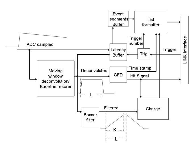

Real-Time Digital Filter and Charge Evaluation
The filtering involves many steps. The first step is the deconvolution of the exponential tail of the pulse shape within an arbitrary time window. The moving window deconvolution method is well documented in the litterature. It is implemented as a finite impulse response filter (FIR). If D0, D1, … Dn, represent the digitized signal samples, and L the span of the moving window, the nth point of the transformed sequence Fn is given by the relation:
(1) 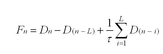

where τ is the exponential time constant of the signal in units of data samples. The deconvolution is useful in the case of a germanium detector to compensate for the differences in ballistic deficit as a function of the rise time of the signal. Depending on the position of the photon interaction, the charge collection time may vary from event to event by as much as 150 nanoseconds. With a preamplifier decay time constant of 50 microseconds, this translates into a fluctuation of the raw signal peak amplitude corresponding to 3 Kev for a 1 Mev gamma. With an analog system, this fluctuation is reduced significantly by using a long filter peaking time, but it never vanishes. With the moving window deconvolution method, the tail pulse shape is transformed into a quasi-rectangular pulse shape, with a duration determined by the span of the moving window. The transformed signal has a leading edge reflecting the shape of the original signal (with a slight correction for the exponential decay), and then reaches a constant maximum value that is exactly the same for a given total charge deposited in the detector whatever the rise-time. The processed signal also returns to zero with no tail.
It can be seen from equation (1) that the first two terms will cancel the DC baseline. However, the sum term that cancels exactly the exponential decay will unfortunately respond to a baseline level with a gain of L/τ. The sum term also limits the effectiveness of the low frequency filtering effect of the first two terms. To alleviate this problem, one can resort to double sampling, or use a baseline restoring scheme. We have chosen this later approach. The baseline restoring process is active only when no signal is present.
At this stage, the filtering is not yet complete. Only the low frequency part of the noise spectrum has been attenuated. The high frequency filtering is performed by applying another FIR transformation to the corrected deconvoluted signal. The most efficient filter for the evaluation of the trend of a noisy straight line (the flat part of the rectangular pulse shape) is the simple floating average transformation, commonly called a boxcar filter:
(2) 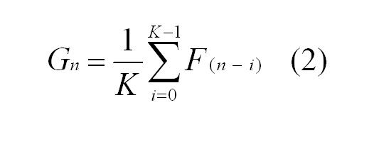

K is chosen to be as close as possible to the size of the flat portion of the rectangular pulse Fn . For a theoretical signal having a zero rise time and an exponential decay with time constant equal to τ, the sequence of points Gn represents a trapeze with a rise time of K, a flat portion of L-K, and a fall time of K. Every point of the flat top part of the pulse is a proper evaluation of the charge. Selecting the maximum value is simple, but it generates a small average bias proportional to the noise. We rather select the measurement point at a pre-determined time after the beginning of the pulse, based on the timing information produced by the CFD discriminator. This amounts to selecting the point at random (as far as the amplitude is concerned) in the flat top region, thereby reducing the bias.
Due to constraint design (the division by τ would involve excessive FPGA resources), we multiply both sides of equation (1) by τ (parameter M), and we do not normalize by the number of points. The result appearing in the event list is given by
It can be scaled down by software when the histograms are constructed.
Digital Constant Fraction Discriminator
Analog constant fraction discriminators (CFD) are widely used to minimize the time walk associated with the detection of signals featuring widely varying amplitudes. The same principle can be applied to digital signal samples, with some differences in the physical implementation. In the VF48 firmware, the implementation reproduces exactly the definition of a CFD: The amplitude of the signal is evaluated, and a threshold is calculated with a predefined fraction. The same signal, delayed through a digital delay line (dual port RAM), is then compared with this calculated threshold until the point immediately below, and the point immediately above the threshold are found. Then, a linear interpolation is performed to evaluate the time corresponding to the threshold crossing. We use time units of 1/16 of the ADC sampling clock period for the interpolation. Often, the rise time is not constant from event to event, as it depends on the position where the electron-holes pairs were created in the crystal. So, it is important to clip the incoming signal to a width equal or shorter than the fastest signal rise time envisioned before the CFD logic. This is achieved by subtracting two samples separated by the proper number of sampling clocks. This has the same effect as the clipping delay line of an analog CFD. The digital CFD produces two outputs: a logic signal synchronized with the ADC clock, when the constant fraction threshold is crossed, and a higher precision time stamp word. The logic signal is used by the trigger logic, whilst the time stamp is part of the event data stream.
Latency and Event Segment Buffers
In order to accommodate for the latency of the trigger system, a circular latency buffer is used to keep the past values of the signal samples available for a time equal or longer than the trigger decision latency. The input of the buffer is either the raw data signal, or the output of the deconvolution logic. This can be selected by a run parameter. The maximum capacity of the latency buffer is presently 512 elements. When a trigger is accepted, this delay allows the recovery of the associated signal since its very beginning. We usually also include a few samples that have occurred before the signal. The latency buffer is implemented in a dual port random access memory running continuously. The read address is equal to the write address minus the number of clock cycles we want to have the data delayed. The signal data is continuously written in the memory, and the delayed data continuously available on the readout port. When a trigger is accepted, a transfer gate is generated for a duration corresponding to the size of the data segment requested, and the data read out is transferred to the next buffer stage: the segment event buffer.
The segment buffer is a simple 1024 word FIFO that stores the waveform data segments, plus two extra bits indicating the beginning and end of these segments. The FIFO is read out asynchronously by the list formatter. The function of the Segment Buffer is to store a few events in order to deramdomize the data flow. The segment buffer also generates an almost full flag that is transmitted to the master trigger system. This is the mechanism that throttles the trigger rate when the data acquisition becomes throughput limited. When the throughput is significantly lower than the system bandwidth, the data acquisition is dead-timeless.
VF48 software
aaa
VF48 MIDAS drivers
vf48.h and vf48.c are distrubuted in the "vme" package together with the test_vf48 and srunner_vme programs.
VF48 test program test_vf48.exe
To build test_vf48.exe, please follow the instructions for using the VME flash programmer.
There are 2 flavours of the program: test_vf48.exe for Universe-II based VME CPUs and test_vf48_gef.exe for Tsi148-based VME CPUs (V7865).
There are 2 flavours of the program: test_vf48 for normal use and test_vf48a built with ROOT can display VF48 data graphically.
To use the program for simple function test of VF48 modules: test_vf48.exe 0xa00000 1000 (test module 0xa00000 with 1000 data samples).
Use the program: test_vf48.exe --addr 0xaN0000 [options] --exit
Available options:
- --addr 0xaN0000
- --reset
- --reconfigure (reconfigure the FPGAs - requires the reset-mod)
- --status
- --exit
- --sleep NNN
- --nloops NNN (number of events to read in each test cycle)
- --regRead RRR (read VME registers)
- --regWrite RRR VVV (write to VME registers)
- --parameterRead GGG PPP (read to VF48 frontend registers - parameters)
- --parameterWrite GGG PPP VVV (write to VF48 frontend registers - parameters)
- --groups GGG_MASK (set the group mask - 6 bits - each bit enables the corresponding VF48 frontend FPGA)
- --samples SSS (set the number of ADC samples to read)
- --suppress VVV (enable channel suppression, set suppression threshold to VVV)
- --start
- --trigger
- --stop
- --dataread WWW
- --pioread
- --eventreadpio
- --eventreadsync
- --noparamtest
- --plot CCC
- --timeoffset TTT
- --timerange TTT
- --time CCC
- --time2 CCC CCC
- --testReg
- --testBusy
- --testSlowReset
Benchmarks
Collector 0x07110817
- time from trigger to data ready in the VME FIFO:
- fully suppressed data (78 words of event headers and channel headers)
- 100 samples: 30 usec
- 200 samples: 70 usec
- 500 samples: 175 usec
- 1000 samples: 350 usec
- unsuppressed data
- 1000 samples: 40 usec
- fully suppressed data (78 words of event headers and channel headers)
- VME block transfers:
- PIO: 1.4 Mbytes/sec
- PIO assisted by the tsi148 DMA engine: 1.4 Mbytes/sec
- BLT32: 20 Mbytes/sec
- MBLT64: 40 Mbytes/sec nominal (depends on the position in the VME crate)
- 2eVME: 50 Mbytes/sec nominal (depends on the position in VME crate)
- 2eSST (implemented but impossible without a hardware mod)
Planned firmware changes
This section is the wish-list for firmware changes, modifications and improvements.
- enable independent operation of the 6 frontend section (each section individually self triggered)
- bigger divisor for super very long time range
- continuous readout mode (number of channels and downsampling has to match available VME bandwidth)
- VME broadcast write to reset timestamps and start acquisition on all VF48 modules at the same time (for individual self-triggered use with timestamp based event builder)
- fix data corruption if ext trigger at the wrong time (when busy)
- fix data corruption in collector (lost first 2 words on event)
- external trigger edge-triggered instead of level triggered
Frontend FPGA:
- (done) do not reset config registers if PLL lock is lost (clock glitch)
- (done) config bit for "reset timestamp on acq start" instead of "on first event"
- (done) config bit for self-triggered mode
- (done) individual data suppression thresholds for each channel (need 8x8 bits: use 16-bit K, L, M and HitDetThr
- (done) counter of self-trigger signal
- charge integration mode
- peak sensing mode
- (done) remember timestamp of last event
Collector FPGA:
- VME broadcast write to start/stop acq (also resets timestamp in frontend)
- ext trigger edge triggered
- counter of ext trigger signals, accepted ext trig (difference is ext trig sent when busy)
- counter of frontend trigger signals
- VME interface: double edge synchronizer to speedup 2rVME block transfer
- event counter
Firmware Update
VF48 firmware is distributed as Altera Quartus POF and SOF files. POF files contain the combined firmware for the VF48 collector and frontend FPGAs and are written into the VF48 flash memory using the AS (active serial) or VME interfaces. SOF files for the VF48 collector and the VF48 frontend contain the firmware for the respective FPGAs. They can be loaded into the VF48 using the JTAG interface or they can be fused together to form a POF file.
- [1] firmware files on the daq-plone site
- [2] Konstantin's collection of historical and experimental firmware files
- [3] vf48 git repository (VF48COL and VF48FE sof files)
Using VME Flash programmer
- obtain and build the VME programmer (srunner_vme) and VF48 test program (test_vf48):
- mkdir $HOME/packages
- cd $HOME/packages
- git clone https://bitbucket.org/ttriumfdaq/vme.git
- cd vme
- make -k srunner_vme.exe srunner_vme_gef.exe test_vf48.exe test_vf48_gef.exe (use the xxx_gef versions of the programs on V7865 VME processors)
- read the firmware revision:
- ./test_vf48_gef.exe --addr 0xa00000 --reset --status --exit
- write firmware into the flash memory using the VME programmer:
- ./srunner_vme_gef.exe -program -64 VF48.pof 0xa000e0
- reboot the VF48 FPGAs into the new firmware (requires "fpga-reset" mod):
- ./test_vf48_gef.exe --addr 0xa00000 --status --reconfigure --status --sleep 1 --reset --status --exit
Using USB Blaster Flash programmer on Linux
Brand new modules and modules with corrupted firmware (not visible on VME bus, cannot use VME flash programmer) have to be programmed through the VF48 AS (Active serial) interface. It is possible to do this using using your VME processor running Linux.
- download and install the Altera Quartus software. (License file not required for writing firmware into flash memory)
- configure Linux file permissions for USB devices - see https://www.triumf.info/wiki/DAQwiki/index.php/SL5install#Configure_USB_device_permissions
- connect the Altera USB Blaster to the VME processor USB port and the VF48 AS port (NOT the JTAG port)
- obtain a VF48 firmware POF file (VF48.pof)
- create the programmer script (change $quartus to point to the location where you installed Quartus)
lxdaq08:firmware$ more load.perl
#!/usr/bin/perl -w

$| = 1;

my $f = shift @ARGV;

die "Cannot read $f: $!\n" unless -r $f;

#my $quartus = "/home/olchansk/altera7.2/quartus7.2";
#my $quartus = "/home/olchansk/altera9.0/quartus";
my $quartus = "/triumfcs/trshare/olchansk/altera/altera9.1/quartus";

my $q = `$quartus/bin/quartus_pgm -l`;
print $q;

$q =~ /1\) (.*)\n/m;
my $b = $1;
print "$b\n";

my $cmd = "$quartus/bin/quartus_pgm -c \"$b\" -m AS -o \"p;$f\"";
print "Running $cmd\n";
system $cmd;

exit 0;
#end
- run "./load.perl VF48.pof"
- observe quartus finds the USB blaster
- observe quartus finds the VF48 flash memory
- observe quartus writes to the flash memory (takes a few minutes)
- disconnect USB blaster from VF48
- power up VF48
- verify VF48 firmware version - run "./test_vf48_gef.exe --addr 0xa00000 --status --exit"
- test VF48 firmware - run "./test_vf48_gef.exe 0xa00000 1000"
Using USB Blaster JTAG programmer on Linux
If you have Altera Quartus SOF firmware files (vf48_col.sof, vf48_fe.sof), you can load them into the VF48 module using the USB Blaster JTAG programmer. Firmware from SOF files are NOT saved into the flash memory. After a power cycle or FPGA reconfiguration, the VF48 loads firmware from the flash memory and any firmware loaded from SOF files is lost.
Sometimes it is convenient to bring up new blank VF48 modules using the JTAG interface by first loading the firmware from SOF files, then, after testing the VME interface, use the VME flash programmer to write the firmware into the flash memory.
- prepare Altera Quartus software, USB file permissions and USB blaster per instructions above
- connect USB blaster to the VF48 JTAG port (NOT the AS port)
- create the programmer script:
lxdaq08:firmware$ more load_jtag.perl
#!/usr/bin/perl -w

$| = 1;

my $col_sof = shift @ARGV;
my $fe_sof  = shift @ARGV;

die "Cannot read collector sof file $col_sof: $!\n" unless -r $col_sof;
die "Cannot read frontend sof file $fe_sof: $!\n" unless -r $fe_sof;

#my $quartus = "/home/quartus/quartus7.2";
#my $quartus = "/home/olchansk/altera7.2/quartus7.2";
#my $quartus = "/home/olchansk/altera9.0/quartus";
my $quartus = "/triumfcs/trshare/olchansk/altera/altera9.1/quartus";

my $q = `$quartus/bin/quartus_pgm -l`;
print $q;

$q =~ /1\) (.*)\n/m;
my $b = $1;
print "$b\n";

#my $cmd = "$quartus/bin/quartus_pgm -c \"$b\" -m JTAG -o \"p;$fe_sof\@3\" ";
my $cmd = "$quartus/bin/quartus_pgm -c \"$b\" -m JTAG -o \"p;$col_sof\@1\" -o \"
p;$fe_sof\@2\" -o \"p;$fe_sof\@3\" -o \"p;$fe_sof\@4\" -o \"p;$fe_sof\@5\" -o \"
p;$fe_sof\@6\" -o \"p;$fe_sof\@7\"";
print "Running $cmd\n";
system $cmd;

exit 0;
#end
- run "./load_jtag.perl vf48_col.sof vf48_fe.sof"
- observe quartus find the USB blaster
- observe quartus find and load the 7 FPGA units
- the SOF loads should go pretty quick
- check the new firmware revision using test_vf48 per instructions above
Firmware Update (OLD)
To do an update, you will need the ByteBlaster II connector connected on the parallel port of your PC and to the connector J3 on the VF48 board. (Or an USB Blaster module)
Then, you must download the programmer on the Altera Website: https://www.altera.com/support/software/download/programming/quartus2/dnl-quartus2_programmer.jsp
Then, you start the program. You change the mode from JTAG to Active Serial Programming. You push the Hardware Setup button and you select ByteBlaster II. Then, you push the Add File button and you select the pof file that we supplied you. After, you click in the Program/Configure case and finally you push the Start button.
When the firmware has been programmed, you must unplug the ByteBlaster II connector from the VF48 board, shut down the power and put it back.
If the green light is on, programming was completed successfully. If the green light is off, did you forget to unplug the ByteBlaster II connector? If no, restart all the procedure.
Label Convention
A label convention is done to name each version that is created. It starts by the firmware main revision. Then, we add respectively the sub revision, the sampling frequency, the system clock frequency and the special features if they exist.
For example, the name VF48_V207_X6_40_20_Alpha.pof is associated to the firmware version 2.0.7 with a sampling frequency of 40 MHz and a system frequency of 20 MHz. The special feature Alpha signifies that this version is done specifically for Alpha project.
Firmware history
Hardware modifications
Reset mod
This modification permits the reset of the module through VME command.
- A new firmware [...] needs to be loaded prior the hardware modification.
- A single wire needs to connect the 2 points displayed in the following 2 images.


Heatsink mod
Required heat-sink for preventing self-shutdown due to overheating [U20 only].
- Make sure the selected heat-sink height is not extending beyond the module width.
- heat-sink insertion
- Remove the plastic screw.
- Remove the voltage regulator.
- clean the 3 vias.
- place some thermal compound inside the heat-sink for thermal contact to the Vreg.
- Place the heat-sink and the Vreg on the top (see picture)
- Mount plastic screw
- Solder the Vreg to the PCB.
- Make sure the isolation is maintained between the Vreg pad and the PCB ground.


TIGC RJ45 mod
Modification for proper VF48-TIGC communication.
- Swap the 2 indicated resistors.
- R78(680) <-> R90(100)
- R79(680) <-> R89(100)
- Add the 100Ohm across the via.

LXe mod
TBW
GEOTOMO mod
TBW