BNMR: Helicity: Difference between revisions
No edit summary |
|||
| (3 intermediate revisions by the same user not shown) | |||
| Line 2: | Line 2: | ||
= Links = | = Links = | ||
<div style="column-count:3;-moz-column-count:3;-webkit-column-count:3"> | <div style="column-count:3;-moz-column-count:3;-webkit-column-count:3"> | ||
* [[BNMR Dual Channel Mode|Dual Channel Mode]] | * [[BNMR Dual Channel Mode|Dual Channel Mode]] | ||
* [[BNMR: Experimental Modes|Experimental Modes]] | * [[BNMR: Experimental Modes|Experimental Modes]] | ||
| Line 14: | Line 13: | ||
* If [[BNMR Dual Channel Mode#Single_Channel_Mode|single channel mode]] at least one system must have helicity flipping disabled, to avoid the experiments fighting each other. | * If [[BNMR Dual Channel Mode#Single_Channel_Mode|single channel mode]] at least one system must have helicity flipping disabled, to avoid the experiments fighting each other. | ||
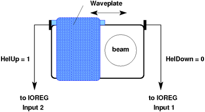
[[Image: | [[Image:Waveplate.png|thumb|400px|center|Figure 1: Helicity Waveplate]] | ||
<br clear=all> | <br clear=all> | ||
== Helicity switch box == | == Helicity switch box == | ||
| Line 27: | Line 23: | ||
The EPICS Helicity switch <code>ILE2:POLSW2:STATLOC</code> must be set to <code>DAQ</code> control if helicity flipping is enabled. If helicity flipping is disabled, the switch can be set for either DAQ or EPICS control. | The EPICS Helicity switch <code>ILE2:POLSW2:STATLOC</code> must be set to <code>DAQ</code> control if helicity flipping is enabled. If helicity flipping is disabled, the switch can be set for either DAQ or EPICS control. | ||
[[Image:helicity_switch_box.png|center|frame|Figure 2 Helicity Switch box]] | [[Image:helicity_switch_box.png|center|frame|Figure 2: Helicity Switch box]] | ||
<br clear=all> | <br clear=all> | ||
| Line 33: | Line 29: | ||
Helicity readback signals have been provided in recent years (Figure 1) so that the state of the helicity can be read with certainty, particularly in dual channel mode. The helicity state is read using a VME NIMIO32 register specially modified for the {{bnmqr|join=and}} experiments (see [[BNMR: DAQ Hardware Connections#NIMIO32|NIMIO32]] for details). Each experiment in provided with a VMEIO32 register. | Helicity readback signals have been provided in recent years (Figure 1) so that the state of the helicity can be read with certainty, particularly in dual channel mode. The helicity state is read using a VME NIMIO32 register specially modified for the {{bnmqr|join=and}} experiments (see [[BNMR: DAQ Hardware Connections#NIMIO32|NIMIO32]] for details). Each experiment in provided with a VMEIO32 register. | ||
It provides a helicity readout for the present state of the helicity (used in single channel mode) as well as a latched helicity readout for dual channel mode. The latched readout latches the helicity state at the time that channel (BNMR or BNQR) has the beam. | It provides a helicity readout for the present state of the helicity (used in single channel mode) as well as a latched helicity readout for dual channel mode. The latched readout latches the helicity state at the time that channel (BNMR or BNQR) has the beam. | ||
== Helicity cabling (and possible cause if helicity remains as "In Transit") == | |||
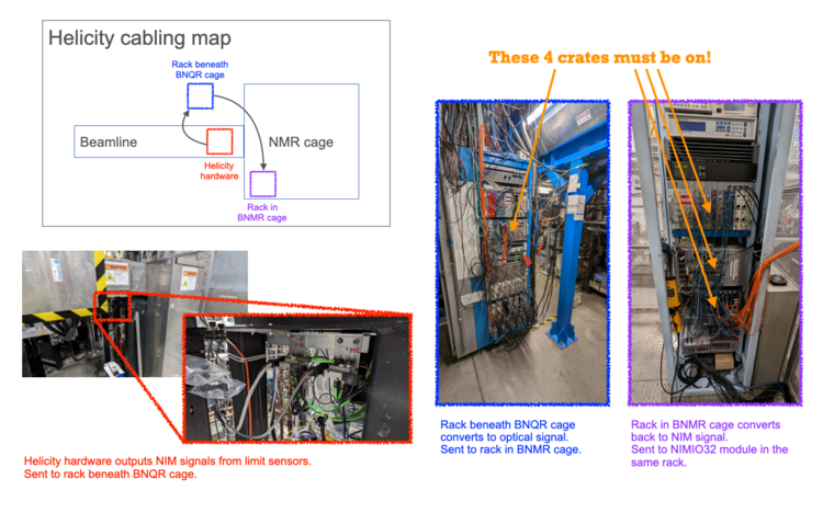
The helicity readback signals are routed from the helicity hardware to the BNMR rack via a NIM->optical->NIM chain. The NIM->optical conversion happens in the rack beneath the BNQR cage. This means that even if you're only running BNMR, you must have the crate beneath the BNQR cage turned on. Otherwise the BNMR will see "off" signals for both limit switches, which it interprets as the waveplate being "In Transit". | |||
See the image below for which crates must be turned on for BNMR to run correctly. If the Helicity is stuck as "In Transit" during a run, verify that all 4 crates are turned on. | |||
[[Image:Helicity_cabling.png|thumb|750px|center|Figure 3: Helicity Cabling]] | |||
<br clear=all> | |||
== Helicity test program == | == Helicity test program == | ||
Latest revision as of 21:40, 6 January 2023
Links
Introduction
The bnmr and bnqr experiments control the helicity via the PPG "POL DRV" output. The helicity is changed using a waveplate (Figure 1) that is moved into and out of the beam. The two helicity states are called "UP" and "DOWN". An experimental parameter flip helicity is provided for each Experimental Mode. When this is set to true, the helicity will be flipped. Some modes flip the helicity after each PPG cycle, others at the end of the scan.
- In dual channel mode, both bnmr and bnqr may have helicity flipping enabled.
- If single channel mode at least one system must have helicity flipping disabled, to avoid the experiments fighting each other.
Helicity switch box
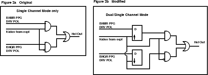
Since both experiments bnmr and bnqr control the same hardware (the helicity plate), signals to drive the helicity from both experiments are connected to a helicity switch box (Rolf's box), Figure 2. These signals are from each experiment's PPG "POL DRV" output. The electronics is edge-driven, so it only changes when it sees an edge. To ensure a particular helicity state at the begin-of-run in single channel mode (e.g. DOWN), the PPG must drive the helicity DOWN-UP-DOWN. In dual channel mode, it is not possible to ensure the required helicity in the way at the begin of run. It is assumed that by the second PPG cycle, the helicity will be in the correct state and the latched helicity readback provides confirmation. The first cycle is always discarded.
The experiment requests the helicity state for its next cycle by setting the PPG "POL DRV" output. In single channel mode, the helicity state is changed immediately. In dual channel mode, the helicity is not changed until that experiment receives the beam (see BNMR Dual Channel Mode#Helicity). A circuit diagram of the helicity switch box as used for single and dual channel modes is shown in Figure 2b. (Figure 2a shows the original, single channel mode only). The D-type flip flops are edge driven, so they only change when an edge from the beam kicker signal is received.
The EPICS Helicity switch ILE2:POLSW2:STATLOC must be set to DAQ control if helicity flipping is enabled. If helicity flipping is disabled, the switch can be set for either DAQ or EPICS control.
Helicity readback
Helicity readback signals have been provided in recent years (Figure 1) so that the state of the helicity can be read with certainty, particularly in dual channel mode. The helicity state is read using a VME NIMIO32 register specially modified for the bnmr and bnqr experiments (see NIMIO32 for details). Each experiment in provided with a VMEIO32 register. It provides a helicity readout for the present state of the helicity (used in single channel mode) as well as a latched helicity readout for dual channel mode. The latched readout latches the helicity state at the time that channel (BNMR or BNQR) has the beam.
Helicity cabling (and possible cause if helicity remains as "In Transit")
The helicity readback signals are routed from the helicity hardware to the BNMR rack via a NIM->optical->NIM chain. The NIM->optical conversion happens in the rack beneath the BNQR cage. This means that even if you're only running BNMR, you must have the crate beneath the BNQR cage turned on. Otherwise the BNMR will see "off" signals for both limit switches, which it interprets as the waveplate being "In Transit".
See the image below for which crates must be turned on for BNMR to run correctly. If the Helicity is stuck as "In Transit" during a run, verify that all 4 crates are turned on.
Helicity test program
There is a MIMIO32/helicity test program on both experiments - see the hardware debugging page.
Helicity sleep time
After the helicity is flipped, experimenters usually want to wait a certain time before the next PPG cycle. This time is the helicity sleep time. In single channel mode, the helicity sleep time parameter can be found with the other experimental parameters on the Settings page.
In dual channel mode, the helicity sleep time is programmed by the experimenters in the timing of the EPICS switching between channels, and the ODB parameter is ignored.
EPICS helicity checks
The ODB parameter /Scanning/Helicity/Settings/Enable checks causes the frontend program to perform the following checks:
- If helicity flipping is enabled
- Verifies that the EPICS Helicity switch
ILE2:POLSW2:STATLOCis set to DAQ control at the start of the run - In single channel mode
- at the start of run the program will attempt to set the helicity to the initial state (HEL_DOWN) and check the read back
- after each helicity flip, the program will check the Helicity state using the Helicity read back values.
- in dual channel mode
- after each helicity flip, after each cycle the program will check the Helicity state using the Helicity read-back latched values.
- Verifies that the EPICS Helicity switch
- If helicity flipping is disabled
- Verifies that the EPICS Helicity switch
ILE2:POLSW2:STATLOCis set to EPICS control at the start of the run
- Verifies that the EPICS Helicity switch
If the readback does not match the set value, the cycle will be skipped and the program will try once more to set the required helicity state.


