BNMR: Dual Channel Mode
Introduction
- dual channel mode
- is when the beam is switched alternately between the two experiments bnmr and bnqr .
- single channel mode
- is when no switching of the beam takes place. and the beam is sent to one of the two experiments (bnmr or bnqr), that experiment is said to be running in #Single Channel Mode.
Switching the beam alternately between the two experiments is done by the Controls Group using the #EPICS switch.
Currently, only Type 2 (TD) experiments can be run in dual channel mode. When running in dual channel mode, both the DAQ systems bnmr and bnqr may be running and taking data, therefore dual channel mode makes better use of the beam time.
In #Single channel mode, only one DAQ system (bnmr or bnqr) is active.
EPICS switch
The EPICS parameter that controls switching is called BNMR:BNQRSW:ENBSWITCHING. Switching must be
- enabled for dual channel mode
- disabled for single channel mode
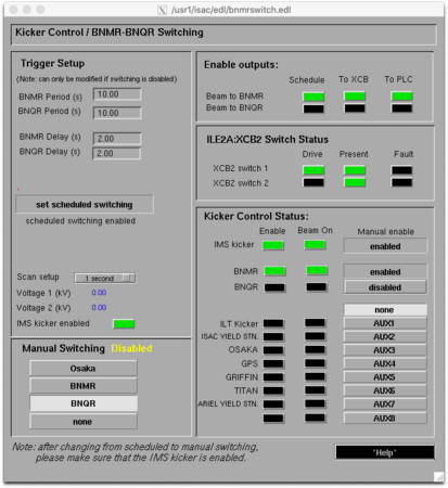
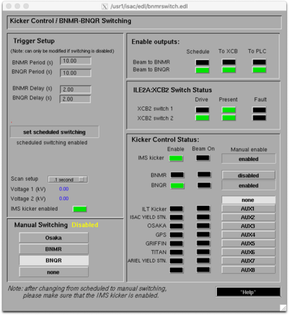
Only the Controls Group can change this switch. The experimenters telephone the Control Room and ask them set this switch as required to run in dual channel or single channel mode. Figure 1 shows the switching set for Dual channel mode (scheduled switching enabled, manual switching disabled). This page can be found on the EPICS page display by clicking "LE Exp." > "ILE2A3 Optics/BNMR" > "beam line switch" button.
It is important to match the timing of the beam switch (BNMR Period/Delay and BNQR Period/Delay) to the PPG Cycle of each experiment (see #Timing).
Experimenters must ensure that the DAQ ODB parameter /Scanning/BNXRCustomCycleLogic/Settings/Enable dual channel mode (called Enable dual channel mode on the custom status page) is set appropriately.
Frontend sanity-checks
Unless performing tests, the ODB parameter /Scanning/BNXRCustomCycleLogic/Settings/Enable EPICS access checks (called Check switching in run start on the custom status page) should be set true. This causes the frontend to validate the beam switching setup:
- Ensures the DAQ Enable dual channel mode flag must match the EPICS
BNMR:BNQRSW:ENBSWITCHINGflag. - Ensures the EPICS
ILE2:BIAS15:VOL.ASGvalue must be set toexpbnmr(for both bnmr and bnqr). - Ensures the EPICS
BNMR:BNQRSW:SCHEDULE.SCANvalue is set to.1 second. If this value isDisabled, then switching never happens and the DAQ does not run correctly.
Helicity
The PPG requests the helicity it requires for the next cycle by a signal from the PPG Output "Pol" connected to the helicity switch box. In Single Channel mode, the helicity is immediately set to this value (UP/DOWN). In Dual Channel mode, the helicity state is not changed until that channel is active (see #Timing).
Starting the PPG
Historically the PPG was started by an "external trigger" signal from the kicker. When an experiment (bnmr or bnqr) was eligible to request beam, a signal was sent from the kicker to the PPG. This signal stayed high for the entire time the experiment was allowed to request beam, and the PPG would start its program as soon as it detected the level was high. Note the PPG only cared about the level of the signal; it did not detect a transition, just the level. If bnmr was eligible for beam for 10s but ran a program that only lasted 7s, the program would start again with 3s of beam remaining! As noted in the #Timing section of this page, it is very important to match the switching schedule to the length of PPG programs being run!
In summer 2022 the PPGs started having issues responding to the external trigger signal. The problem mostly affected bnqr, but did also appear on bnmr one time. The PPG registers would show that it was in "external trigger" mode, would show that it was detecting the trigger signal changing between high/low, but would not start the program when it was supposed to! The only solution was to reboot the VME crate, which is both tedious and sometimes problematic if experimenters are doing careful instrument control via CAMP, as the PPG and CAMP server are both in the same crate. Note it was still possible to start the program via a software signal, just not via hardware.
For this reason, a new option was added to the frontend code to allow it start the program via software. It checks the state of the BNMR:BNQRSW:STATBNMRENB or BNMR:BNQRSW:STATBNQRENB PVs to see whether it is "off" or "on". When it is "on" (and the PPG isn't already running), it starts the PPG via a software signal. This appears to be more robust, but does involve a lot of polling of EPICS to ensure we start the PPG program as soon as possible after we become eligible for beam.
The RF calculator program has functionality to force which behaviour is used (hardware or software start). The choice is currently hard-coded with force_epics_for_dual_channel = True in bnxr_common.rf_calculator_fe.RFCalculatorEquipment.check_mode_params(), which is called at the start of each run. This flag then sets the ODB keys:
- /Scanning/BNXRCustomCycleLogic/Settings/Dual channel start on beam enb to true, to ensure the frontend will start the PPG
- /Equipment/PPGCompiler/Settings/Use external trigger to false, to ensure the PPG gets configured to not respond to the external trigger (we don't want the software and hardware methods to compete with each other)
Timing
Figure 2 shows a timing diagram for dual channel mode.
In dual channel mode, the PPG Cycle is started by an external signal (PPG Start/Beam Ready) that occurs at the end of the BNMR or BNQR Delay (Figure 2). Usually the PPG cycle is divided into 3 regions: prebeam, beam on, and post-beam. Once the PPG cycle is started, the PPG Output "Beam On" controls when and how long the beam is on. The timing of these signals is controlled by parameters set for each PPG timing scheme.
The experimenter must be careful to set the timing of the BNMR and BNQR cycles such that the Beam On period of the PPG Cycle has finished before the beam is switched to the other channel. The post-beam period of one channel generally overlaps part of the cycle of the other channel. This timing is controlled by the EPICS parameters BNMR Period (s), BNQR Period (s), BNMR Delay (s), BNQR Delay (s). These are available on the EPICS Kicker Control/BNMR-BNQR Switching page (Figure 1). The BNMR and BNQR Delays must be set to give the Helicity time to change. They are equivalent to the ODB parameter Helicity Sleep time in Single Channel mode. This parameter is ignored in dual channel mode.
Single Channel Mode
In single channel mode, the beam is directed to one of the channels (bnmr or bnqr). The #EPICS switch and the DAQ ODB parameter /Scanning/BNXRCustomCycleLogic/Settings/Dual channel mode must both be set to off/false/disabled.
Only the DAQ system for the channel with the beam should be running. The other DAQ system must not be run (except by "experts" for #Testing under certain conditions). This is because there is currently NO CHECK against both DAQ systems running simultaneously in single channel mode, and both trying to flip the helicity. This would ruin the data for the active channel with the beam.
In single channel mode, the PPG Cycle is started by a software command given by the frontend.
Testing
Both DAQ systems may be run in single channel mode simultaneously for testing under certain conditions. Outside the beam period, it is sufficient to disable helicity flipping on one of the DAQ systems, so that for example BNMR flips the helicity, and BNQR does not. In that case, the Helicity check must be disabled on BNQR.
Alternatively, and especially during the beam period, the beam on/off and helicity outputs from the PPG on the test system should be disconnected so that the test DAQ cannot interfere with the data taking run. In this case, helicity flipping can be enabled on the disconnected system (but helicity is not actually flipped), but Helicity check must be disabled.


